Owners Manual
Page 7
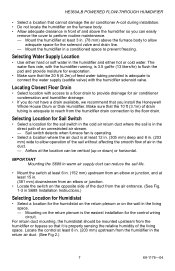
... from the air entrance. (See Fig. 1-3 in S688 Installation Instructions.) Selecting Location for Humidistat • Select a location for the solenoid valve and drain line. - Make sure that the 10 ft (3.1m) of the living space. Selecting Water Supply Location • Use ...least 8 in. (203 mm) upstream from the humidifier drain connection to allow operation of the sail without affecting the smooth flow of and above the humidifier so you install the Honeywell Whole House Drum or Disk Humidifier. HE360A,B POWERED FLOW-THROUGH HUMIDIFIER • Select a location that cannot damage the...
... from the air entrance. (See Fig. 1-3 in S688 Installation Instructions.) Selecting Location for Humidistat • Select a location for the solenoid valve and drain line. - Make sure that the 10 ft (3.1m) of the living space. Selecting Water Supply Location • Use ...least 8 in. (203 mm) upstream from the humidifier drain connection to allow operation of the sail without affecting the smooth flow of and above the humidifier so you install the Honeywell Whole House Drum or Disk Humidifier. HE360A,B POWERED FLOW-THROUGH HUMIDIFIER • Select a location that cannot damage the...
Owners Manual
Page 10
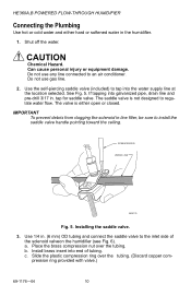
... the solenoid valveon the humidifier (see Fig. 6). SCREW DRIVER WATER LINE M20175 Fig. 5. Install brass insert into galvanized pipe, drain line and pre-drill 3/17 in -line filter, be sure to install the saddle valve handle pointing toward the ceiling. tap for saddle valve. Can cause personal injury or equipment damage. HE360A,B POWERED FLOW-THROUGH HUMIDIFIER Connecting...
... the solenoid valveon the humidifier (see Fig. 6). SCREW DRIVER WATER LINE M20175 Fig. 5. Install brass insert into galvanized pipe, drain line and pre-drill 3/17 in -line filter, be sure to install the saddle valve handle pointing toward the ceiling. tap for saddle valve. Can cause personal injury or equipment damage. HE360A,B POWERED FLOW-THROUGH HUMIDIFIER Connecting...
Owners Manual
Page 11
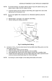
...tubing. 4. b. NOTE: Do not over the drain nipple on the humidifier. for correct drainage. BRASS COMPRESSION NUT PLASTIC COMPRESSION RING BRASS INSERT M20176 Fig. 6. a. c. ment and ensure downward slope for solenoid valve fitting. d. Push the tubing over -tighten the compression nut. Fasten the...-04 HE360A,B POWERED FLOW-THROUGH HUMIDIFIER NOTE: To prevent leaking, use duct tape) along the route to prevent move- Hand-tighten the clamp around the tubing to secure the humidifier drain. Insert the tubing into the solenoid valve fitting and support the valve while ...
...tubing. 4. b. NOTE: Do not over the drain nipple on the humidifier. for correct drainage. BRASS COMPRESSION NUT PLASTIC COMPRESSION RING BRASS INSERT M20176 Fig. 6. a. c. ment and ensure downward slope for solenoid valve fitting. d. Push the tubing over -tighten the compression nut. Fasten the...-04 HE360A,B POWERED FLOW-THROUGH HUMIDIFIER NOTE: To prevent leaking, use duct tape) along the route to prevent move- Hand-tighten the clamp around the tubing to secure the humidifier drain. Insert the tubing into the solenoid valve fitting and support the valve while ...
Owners Manual
Page 16
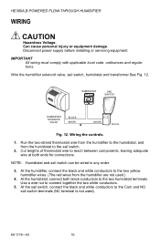
... (NC terminal is not used .) 4. Wire the humidifier solenoid valve, sail switch, humidistat and transformer.See Fig. 12. At the sail switch, connect the black and white conductors to the two yellow humidifier wires. (The red wires from the humidistat to the two humidistat terminals. HE360A,B POWERED FLOW-THROUGH HUMIDIFIER WIRING CAUTION Hazardous Voltage. Can cause personal...
... (NC terminal is not used .) 4. Wire the humidifier solenoid valve, sail switch, humidistat and transformer.See Fig. 12. At the sail switch, connect the black and white conductors to the two yellow humidifier wires. (The red wires from the humidistat to the two humidistat terminals. HE360A,B POWERED FLOW-THROUGH HUMIDIFIER WIRING CAUTION Hazardous Voltage. Can cause personal...
Owners Manual
Page 21
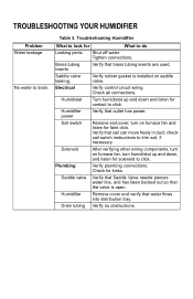
... has power. Drain tubing Verify no obstructions. Table 3. Humidifier power Verify that sail can move freely in duct; Plumbing Verify plumbing connections. Shut off water. Verify rubber gasket is open. Sail switch Remove sail cover; Saddle valve Verify that Saddle Valve needle ...listen for What to look for faint click. Electrical Verify control circuit wiring. Check for solenoid to click. Check all connections. Saddle valve leaking. Humidifier Remove cover and verify that brass tubing inserts are used. Humidistat Turn humidistat up and ...
... has power. Drain tubing Verify no obstructions. Table 3. Humidifier power Verify that sail can move freely in duct; Plumbing Verify plumbing connections. Shut off water. Verify rubber gasket is open. Sail switch Remove sail cover; Saddle valve Verify that Saddle Valve needle ...listen for What to look for faint click. Electrical Verify control circuit wiring. Check for solenoid to click. Check all connections. Saddle valve leaking. Humidifier Remove cover and verify that brass tubing inserts are used. Humidistat Turn humidistat up and ...


