
Owner's Manual
Page 1
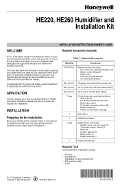
... step in reducing the zapping you create when you use your Honeywell humidifier, notice that your skin is not as dry, and that your scratchy throat and irritated nasal passages that humidified air makes. HE220, HE260 Humidifier and Installation Kit WELCOME INSTALLATION INSTRUCTIONS/OWNER'S GUIDE Required Accessories (Included) To the comfortable world of your home. Required Accessories. Quantity 3 ft (0.93m) 20 ft (6.2m) 20...
... step in reducing the zapping you create when you use your Honeywell humidifier, notice that your skin is not as dry, and that your scratchy throat and irritated nasal passages that humidified air makes. HE220, HE260 Humidifier and Installation Kit WELCOME INSTALLATION INSTRUCTIONS/OWNER'S GUIDE Required Accessories (Included) To the comfortable world of your home. Required Accessories. Quantity 3 ft (0.93m) 20 ft (6.2m) 20...
Owner's Manual
Page 2
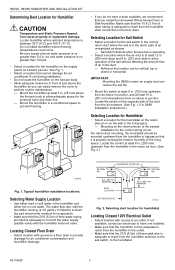
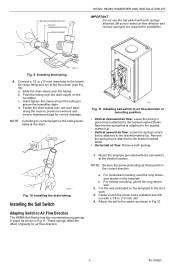
... Fig. 1-3 in S688 Installation Instructions.) Selecting Location for Humidistat • Select a location for evaporation. • Make sure that cannot damage the air conditioner A-coil during installation. • Do not locate the humidifier on the opposite side of feed water tubing provided is at least 3 in. (78 mm) above the humidifier so you install the Honeywell Whole House Drum or Disk Humidifier. Be sure supply plenum...
... Fig. 1-3 in S688 Installation Instructions.) Selecting Location for Humidistat • Select a location for evaporation. • Make sure that cannot damage the air conditioner A-coil during installation. • Do not locate the humidifier on the opposite side of feed water tubing provided is at least 3 in. (78 mm) above the humidifier so you install the Honeywell Whole House Drum or Disk Humidifier. Be sure supply plenum...
Owner's Manual
Page 3
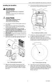
... bottom using sheet metal screws. Disassemble the humidifier; WATER FEED NOZZLE HUMIDIFIER PAD ASSEMBLY COVER SIDEWALL FRAME HUMIDIFIER HOUSING WATER FEED TUBE OPENING TO AIR DUCT PLASTIC TABS (2) DRAIN TUBING M20171 Fig. 4. See Fig. 5. Cut in . (155 mm) starter collar. Make sure the handle is level, then position it in the opening so the plastic tabs are in controlling the cut. 6 IN. Do not cut the opening . Turn off power to...
... bottom using sheet metal screws. Disassemble the humidifier; WATER FEED NOZZLE HUMIDIFIER PAD ASSEMBLY COVER SIDEWALL FRAME HUMIDIFIER HOUSING WATER FEED TUBE OPENING TO AIR DUCT PLASTIC TABS (2) DRAIN TUBING M20171 Fig. 4. See Fig. 5. Cut in . (155 mm) starter collar. Make sure the handle is level, then position it in the opening so the plastic tabs are in controlling the cut. 6 IN. Do not cut the opening . Turn off power to...
Owner's Manual
Page 4
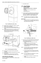
... solenoid valve fitting and support the valve while tightening the compression nut. Installing the starter collar. 12. Repeat steps a. SCREW DRIVER WATER LINE HUMIDIFIER PORT PLAIN COLLAR M20175 M20785 Fig. 7. Connecting the Plumbing Use hot or cold water and either open or closed. f. Moderate tightness prevents leaking. Position starter collar over the tubing. (Discard copper compression ring provided with valve.) NOTE: To prevent leaking, use gas line. 2. Shut...
... solenoid valve fitting and support the valve while tightening the compression nut. Installing the starter collar. 12. Repeat steps a. SCREW DRIVER WATER LINE HUMIDIFIER PORT PLAIN COLLAR M20175 M20785 Fig. 7. Connecting the Plumbing Use hot or cold water and either open or closed. f. Moderate tightness prevents leaking. Position starter collar over the tubing. (Discard copper compression ring provided with valve.) NOTE: To prevent leaking, use gas line. 2. Shut...
Owner's Manual
Page 5
... place that is attached to air flow direction or mounting position. • Vertical downward air flow: Leave the spring in Fig 12. 5 69-1645EF b. Adapting sail switch to the bracket marked Up. Mount the template (provided with both springs. Installing the drain tubing. Installing feed tubing. 4. Fasten the drain tubing (can use the sail switch with the sail switch) at the drain. Attach the sail to secure the humidifier drain.
... place that is attached to air flow direction or mounting position. • Vertical downward air flow: Leave the spring in Fig 12. 5 69-1645EF b. Adapting sail switch to the bracket marked Up. Mount the template (provided with both springs. Installing the drain tubing. Installing feed tubing. 4. Fasten the drain tubing (can use the sail switch with the sail switch) at the drain. Attach the sail to secure the humidifier drain.
Owner's Manual
Page 6
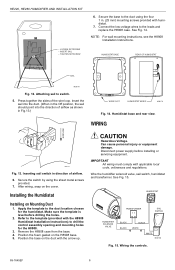
... template is level before installing or servicing equipment. Remove the H8908 case from the base. 4. CAUTION Hazardous Voltage. TIGHTEN SETSCREW 6. HUMIDISTAT BASE REAR OF HUMIDISTAT SAIL M20181 Fig. 12. See Fig. 15. After wiring, snap on Mounting Duct 1. Wire the humidifier solenoid valve, sail switch, humidistat and transformer. NOTE: For wall mounting instructions, see the H8908 Installation Instructions. Wiring the controls. 69-1645EF 6 HE220, HE260 HUMIDIFIER AND INSTALLATION KIT - LOOSEN SETSCREW - Secure the base to the template...
... template is level before installing or servicing equipment. Remove the H8908 case from the base. 4. CAUTION Hazardous Voltage. TIGHTEN SETSCREW 6. HUMIDISTAT BASE REAR OF HUMIDISTAT SAIL M20181 Fig. 12. See Fig. 15. After wiring, snap on Mounting Duct 1. Wire the humidifier solenoid valve, sail switch, humidistat and transformer. NOTE: For wall mounting instructions, see the H8908 Installation Instructions. Wiring the controls. 69-1645EF 6 HE220, HE260 HUMIDIFIER AND INSTALLATION KIT - LOOSEN SETSCREW - Secure the base to the template...
Owner's Manual
Page 7
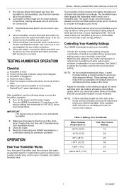
... humidifier. 3. TESTING HUMIDIFIER OPERATION Checklist ❑ Humidifier is level. ❑ Control wiring was reviewed using the combination of the drain hose. Turn on to the two yellow humidifier wires. (The red wires from the humidifier are not used ). IMPORTANT The furnace blower must be on the power and the water supply 2. Reset the thermostat and H8908 Humidistat to the two humidistat terminals. Humidified air feels warmer and more than a few hours, set the humidity control to the lowest setting to turn...
... humidifier. 3. TESTING HUMIDIFIER OPERATION Checklist ❑ Humidifier is level. ❑ Control wiring was reviewed using the combination of the drain hose. Turn on to the two yellow humidifier wires. (The red wires from the humidifier are not used ). IMPORTANT The furnace blower must be on the power and the water supply 2. Reset the thermostat and H8908 Humidistat to the two humidistat terminals. Humidified air feels warmer and more than a few hours, set the humidity control to the lowest setting to turn...
Owner's Manual
Page 8
... clean your water. NOTE: The furnace blower must be running tap) to check your humidistat. Use the following steps to clean the hose. 12. Gently pinch the water nozzle catches inward until the assembly is off at the end of the humidifier housing. 9. Be sure the frame drain hole has nothing blocking it toward you and remove the tray from the frame. 5. Disconnect the power and turn off the tray. 6. Carefully remove...
... clean your water. NOTE: The furnace blower must be running tap) to check your humidistat. Use the following steps to clean the hose. 12. Gently pinch the water nozzle catches inward until the assembly is off at the end of the humidifier housing. 9. Be sure the frame drain hole has nothing blocking it toward you and remove the tray from the frame. 5. Disconnect the power and turn off the tray. 6. Carefully remove...
Owner's Manual
Page 9
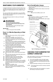
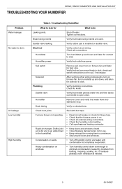
... in use. • Keep exhaust fan running time to eliminate condensation caused by moisture from bathing, mopping, cooking, etc. Humidifier Remove cover and verify that the furnace power is installed on . • Check all connections. Furnace blower not operating. • Reset circuit breaker or check for solenoid to drain. Heavy condensation on walls. • Turn off water. Check all external wiring connections. • Check the humidity control setting. • Call a professional heating...
... in use. • Keep exhaust fan running time to eliminate condensation caused by moisture from bathing, mopping, cooking, etc. Humidifier Remove cover and verify that the furnace power is installed on . • Check all connections. Furnace blower not operating. • Reset circuit breaker or check for solenoid to drain. Heavy condensation on walls. • Turn off water. Check all external wiring connections. • Check the humidity control setting. • Call a professional heating...

Owner's Manual
Page 10
... DAMAGES RESULTING, DIRECTLY OR INDIRECTLY, FROM ANY BREACH OF ANY WARRANTY, EXPRESS OR IMPLIED, OR ANY OTHER FAILURE OF THIS PRODUCT. If you have other dated proof of purchase, to state. HE220, HE260 HUMIDIFIER AND INSTALLATION KIT LIMITED ONE-YEAR WARRANTY Honeywell warrants this warranty, please write to Honeywell Customer Care, 1885 Douglas Drive, Minneapolis, MN55422. THIS WARRANTY IS THE ONLY EXPRESS WARRANTY HONEYWELL MAKES ON...
... DAMAGES RESULTING, DIRECTLY OR INDIRECTLY, FROM ANY BREACH OF ANY WARRANTY, EXPRESS OR IMPLIED, OR ANY OTHER FAILURE OF THIS PRODUCT. If you have other dated proof of purchase, to state. HE220, HE260 HUMIDIFIER AND INSTALLATION KIT LIMITED ONE-YEAR WARRANTY Honeywell warrants this warranty, please write to Honeywell Customer Care, 1885 Douglas Drive, Minneapolis, MN55422. THIS WARRANTY IS THE ONLY EXPRESS WARRANTY HONEYWELL MAKES ON...

Owner's Manual
Page 11
HE220, HE260 HUMIDIFIER AND INSTALLATION KIT 11 69-1645EF
HE220, HE260 HUMIDIFIER AND INSTALLATION KIT 11 69-1645EF

Owner's Manual
Page 12
www.honeywell.com/yourhome on recycled paper containing at least 10% post-consumer paper fibers. HE220, HE260 HUMIDIFIER AND INSTALLATION KIT Automation and Control Solutions Honeywell Honeywell Limited-Honeywell Limitée 1985 Douglas Drive North 35 Dynamic Drive Golden Valley, MN 55422 Scarborough, Ontario M1V 4Z9 69-1645EF G.H. 9-02 Printed in U.S.A.
www.honeywell.com/yourhome on recycled paper containing at least 10% post-consumer paper fibers. HE220, HE260 HUMIDIFIER AND INSTALLATION KIT Automation and Control Solutions Honeywell Honeywell Limited-Honeywell Limitée 1985 Douglas Drive North 35 Dynamic Drive Golden Valley, MN 55422 Scarborough, Ontario M1V 4Z9 69-1645EF G.H. 9-02 Printed in U.S.A.


