
Owner's Manual
Page 1
... 5. All Rights Reserved 69-1676-1 Registered Trademark • Patents Pending Copyright © 2004 Honeywell International Inc. Operating the Thermostat...13 Step 12. CT8775A,C THE DIGITAL ROUND™ NON-PROGRAMMABLE THERMOSTATS CT8775A Heat Only Thermostat (20 to 30 Vac) and CT8775C Heating-Cooling Thermostat (20 to 30 Vac) Para obtener un documento con las instrucciones en espa...
... 5. All Rights Reserved 69-1676-1 Registered Trademark • Patents Pending Copyright © 2004 Honeywell International Inc. Operating the Thermostat...13 Step 12. CT8775A,C THE DIGITAL ROUND™ NON-PROGRAMMABLE THERMOSTATS CT8775A Heat Only Thermostat (20 to 30 Vac) and CT8775C Heating-Cooling Thermostat (20 to 30 Vac) Para obtener un documento con las instrucciones en espa...
Owner's Manual
Page 2
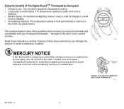
...temperature setting is held permanently in memory in a sealed tube. Read these instructions can arise as you become familiar and comfortable with your Honeywell thermostat - Contact your old control in the trash. The temperature reading is replacing a control that can damage the product or cause a hazardous... proper disposal of an old control containing mercury in the event of a power failure. MERCURY NOTICE If this thermostat is easily seen from a distance. • Backlit display. COOLER WARMER ROOM SET M19582 MERCURY SWITCH TYPICAL LOCATION OF A MERCURY SWITCH...
...temperature setting is held permanently in memory in a sealed tube. Read these instructions can arise as you become familiar and comfortable with your Honeywell thermostat - Contact your old control in the trash. The temperature reading is replacing a control that can damage the product or cause a hazardous... proper disposal of an old control containing mercury in the event of a power failure. MERCURY NOTICE If this thermostat is easily seen from a distance. • Backlit display. COOLER WARMER ROOM SET M19582 MERCURY SWITCH TYPICAL LOCATION OF A MERCURY SWITCH...
Owner's Manual
Page 3
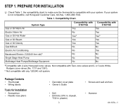
... CT8775A Yes No Yesa Yes Yes No No No No No Compatibility with CT8775C Yes Yes Yesa Yes Yes No Yes No Yes No aCompatible with Taco zone valves and 2- Package Contents • Thermostat • Wiring labels Tools for Installation • Screwdriver • Needle... nose pliers • Decorator cover plate • Owner's Guide • Drill • Drill bits (3/16 in . drywall, 7/32 in . Compatibility Chart. Not compatible with 2-wire Honeywell zone valves. or 3-wire...
... CT8775A Yes No Yesa Yes Yes No No No No No Compatibility with CT8775C Yes Yes Yesa Yes Yes No Yes No Yes No aCompatible with Taco zone valves and 2- Package Contents • Thermostat • Wiring labels Tools for Installation • Screwdriver • Needle... nose pliers • Decorator cover plate • Owner's Guide • Drill • Drill bits (3/16 in . drywall, 7/32 in . Compatibility Chart. Not compatible with 2-wire Honeywell zone valves. or 3-wire...
Owner's Manual
Page 4
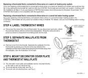
... is connected to make sure they will work with the operation of these systems. For information about which thermostats will not interfere with your system, call Honeywell Customer Care, at Step 4. Place the wires where they work , contact your heating and cooling systems to three ...wires on a warm air heating only system. • A thermostat that may have either system does not work properly. This thermostat is below 50°F ...
... is connected to make sure they will work with the operation of these systems. For information about which thermostats will not interfere with your system, call Honeywell Customer Care, at Step 4. Place the wires where they work , contact your heating and cooling systems to three ...wires on a warm air heating only system. • A thermostat that may have either system does not work properly. This thermostat is below 50°F ...
Owner's Manual
Page 5
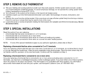
... can be mounted directly on the wall or onto an electrical box. ❑ To mount directly to keep them from the thermostat by setting the thermostat fan switch to ON, the CT8775C Thermostat will only work with your system. Wrap the wires around a pencil as shown to the wall, see Fig. 1. ❑ To mount...
... can be mounted directly on the wall or onto an electrical box. ❑ To mount directly to keep them from the thermostat by setting the thermostat fan switch to ON, the CT8775C Thermostat will only work with your system. Wrap the wires around a pencil as shown to the wall, see Fig. 1. ❑ To mount...
Owner's Manual
Page 8
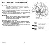
... IMPORTANT Remove the factory-installed jumper connecting terminals R and Rc on the CT8775C Thermostat if wires will be connected to the labels you placed on the wires when you removed the Y old thermostat (see pp 16-17. ❑ Loosen the terminal screws. Wraparound and... straight connections are both of these terminals. ❑ For wiring diagrams, see illustration). ❑ Match the letter of your old thermostat wire with the corresponding W terminal letter on your local R heating/air conditioning contractor. M19496 69-1676-1 8 STEP 7. Tighten the terminals...
... IMPORTANT Remove the factory-installed jumper connecting terminals R and Rc on the CT8775C Thermostat if wires will be connected to the labels you placed on the wires when you removed the Y old thermostat (see pp 16-17. ❑ Loosen the terminal screws. Wraparound and... straight connections are both of these terminals. ❑ For wiring diagrams, see illustration). ❑ Match the letter of your old thermostat wire with the corresponding W terminal letter on your local R heating/air conditioning contractor. M19496 69-1676-1 8 STEP 7. Tighten the terminals...
Owner's Manual
Page 9
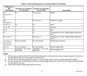
... stage heat. NOTES: 1. Connect O to a single stage heat pump. installation. Tape off wire with electri- Terminal Designations on the new thermostat and connect Rh to R and R to both R and Rc on CT8775C R R (see Note 2) Power Description - Rc (see Note 2) W Y G O B (see Note 3) W2, H2 Y2 Connect to both O and B when wiring to O. Changeover...
... stage heat. NOTES: 1. Connect O to a single stage heat pump. installation. Tape off wire with electri- Terminal Designations on the new thermostat and connect Rh to R and R to both R and Rc on CT8775C R R (see Note 2) Power Description - Rc (see Note 2) W Y G O B (see Note 3) W2, H2 Y2 Connect to both O and B when wiring to O. Changeover...
Owner's Manual
Page 10
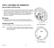
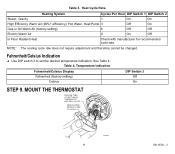
...adjust the heat cycle rate or the Fahrenheit/Celsius indication, locate DIP switch 1, 2 and 3 on the wallplate (see Fig. 3). BACK OF THERMOSTAT ON 123 69-1676-1 DIP SWITCH M19567 Fig. 4. FUEL SWITCH M19497 Fig. 3. STEP 8. DIP switch. 10 The E setting allows the fan ...to E. CUSTOMIZE THE THERMOSTAT Set Fuel Switch (CT8775C Only) ❑ To adjust the fuel switch, locate the switch labeled E/F on the back of the thermostat. NOTE: The CT8775A,C Thermostats will provide optimal temperature control if DIP switches 1 and 2 are set...
...adjust the heat cycle rate or the Fahrenheit/Celsius indication, locate DIP switch 1, 2 and 3 on the wallplate (see Fig. 3). BACK OF THERMOSTAT ON 123 69-1676-1 DIP SWITCH M19567 Fig. 4. FUEL SWITCH M19497 Fig. 3. STEP 8. DIP switch. 10 The E setting allows the fan ...to E. CUSTOMIZE THE THERMOSTAT Set Fuel Switch (CT8775C Only) ❑ To adjust the fuel switch, locate the switch labeled E/F on the back of the thermostat. NOTE: The CT8775A,C Thermostats will provide optimal temperature control if DIP switches 1 and 2 are set...
Owner's Manual
Page 11
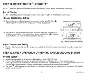
Fahrenheit/Celsius Indication ❑ Use DIP switch 3 to set the desired temperature indication. MOUNT THE THERMOSTAT ENGAGE TABS AT BOTTOM OF THERMOSTAT AND WALL PLATE. Heat Cycle Rate. NOTE: The cooling cycle rate does not require adjustment and therefore cannot be changed. Temperature Indication. See Table 4. Fahrenheit/...
Fahrenheit/Celsius Indication ❑ Use DIP switch 3 to set the desired temperature indication. MOUNT THE THERMOSTAT ENGAGE TABS AT BOTTOM OF THERMOSTAT AND WALL PLATE. Heat Cycle Rate. NOTE: The cooling cycle rate does not require adjustment and therefore cannot be changed. Temperature Indication. See Table 4. Fahrenheit/...
Owner's Manual
Page 12
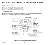
...(see Fig. 5) ❑ Heat: The thermostat controls your heating system. ❑ Off: Both the heating and cooling systems are off. ❑ Cool: The thermostat controls your cooling system. Use for most homes. SET THE SYSTEM AND FAN SWITCHES (CT8775C ONLY) System Switch (see Fig. 5) &#...10065; Fan Auto: Normal setting for improved air circulation. 69-1676-1 (CT8775C ONLY) SELECTS COOL/OFF/HEAT (CT8775C ONLY) SELECTS ON/...
...(see Fig. 5) ❑ Heat: The thermostat controls your heating system. ❑ Off: Both the heating and cooling systems are off. ❑ Cool: The thermostat controls your cooling system. Use for most homes. SET THE SYSTEM AND FAN SWITCHES (CT8775C ONLY) System Switch (see Fig. 5) &#...10065; Fan Auto: Normal setting for improved air circulation. 69-1676-1 (CT8775C ONLY) SELECTS COOL/OFF/HEAT (CT8775C ONLY) SELECTS ON/...
Owner's Manual
Page 13
...CHECK OPERATION OF HEATING AND/OR COOLING SYSTEM Heating System ❑ Slide the system switch to Heat and the Fan switch to Auto (CT8775C only). ❑ Turn the dial clockwise to raise the temperature setting several degrees above the room temperature. ❑ A flame will...memory. The heating system should turn off. 13 69-1676-1 M19489 Fig. 6. Room Temperature Display. STEP 12. STEP 11. OPERATING THE THERMOSTAT NOTE: Batteries are not required because the temperature setting is displayed. ROOM SET ❑ If a change to the temperature setting is displayed....
...CHECK OPERATION OF HEATING AND/OR COOLING SYSTEM Heating System ❑ Slide the system switch to Heat and the Fan switch to Auto (CT8775C only). ❑ Turn the dial clockwise to raise the temperature setting several degrees above the room temperature. ❑ A flame will...memory. The heating system should turn off. 13 69-1676-1 M19489 Fig. 6. Room Temperature Display. STEP 12. STEP 11. OPERATING THE THERMOSTAT NOTE: Batteries are not required because the temperature setting is displayed. ROOM SET ❑ If a change to the temperature setting is displayed....
Owner's Manual
Page 14
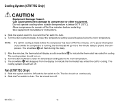
... and the Fan switch to Auto. ❑ Turn the dial counterclockwise to On. The fan should turn off . 69-1676-1 14 Fan (CT8775C Only) ❑ Slide the system switch to Off and the fan switch to lower the temperature setting several degrees below 50°F (10°...;C). Do not operate cooling when outside temperature is running, the thermostat will display a solid snowflake to compressor or other equipment. The cooling system should turn off . The fan should run continuously. ❑ Slide...
... and the Fan switch to Auto. ❑ Turn the dial counterclockwise to On. The fan should turn off . 69-1676-1 14 Fan (CT8775C Only) ❑ Slide the system switch to Off and the fan switch to lower the temperature setting several degrees below 50°F (10°...;C). Do not operate cooling when outside temperature is running, the thermostat will display a solid snowflake to compressor or other equipment. The cooling system should turn off . The fan should run continuously. ❑ Slide...
Owner's Manual
Page 15
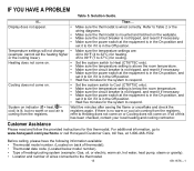
.... IF YOU HAVE A PROBLEM Table 5. Display does not appear. • Make sure the thermostat is in the Off position. For additional information, go to www.honeywell.com/yourhome or call Honeywell Customer Care, toll free, at the equipment is in the On position and set it to ...Heating does not come on or Cooling does not come on. Before calling, please have the following information available: • Thermostat model number. (Located on . • Set the system switch to Heat (CT8775C...
.... IF YOU HAVE A PROBLEM Table 5. Display does not appear. • Make sure the thermostat is in the Off position. For additional information, go to www.honeywell.com/yourhome or call Honeywell Customer Care, toll free, at the equipment is in the On position and set it to ...Heating does not come on or Cooling does not come on. Before calling, please have the following information available: • Thermostat model number. (Located on . • Set the system switch to Heat (CT8775C...
Owner's Manual
Page 17
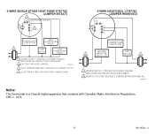
... DISCONNECT MEANS AND OVERLOAD PROTECTION AS REQUIRED. 2 FACTORY INSTALLED JUMPER. O B Rc 2 G R Y W COMPRESSOR CONTACTOR HEATING 1 RELAY OR VALVE COIL FAN RELAY 1 1 POWER SUPPLY. M19454 Notice: This thermostat is a Class B digital apparatus that complies with Canadian Radio Interference Regulations, CRC c. 1374. 17 69-1676-1 M19453 3 USE A JUMPER WIRE (NOT SUPPLIED) TO CONNECT W TO...
... DISCONNECT MEANS AND OVERLOAD PROTECTION AS REQUIRED. 2 FACTORY INSTALLED JUMPER. O B Rc 2 G R Y W COMPRESSOR CONTACTOR HEATING 1 RELAY OR VALVE COIL FAN RELAY 1 1 POWER SUPPLY. M19454 Notice: This thermostat is a Class B digital apparatus that complies with Canadian Radio Interference Regulations, CRC c. 1374. 17 69-1676-1 M19453 3 USE A JUMPER WIRE (NOT SUPPLIED) TO CONNECT W TO...


