

Owner's Manual
Page 1
... 1. Prepare for Installation ...5 Step 2. Set the Fan and System Switches ...19 If You Have a Problem ...20 Smart Response™ Technology ...21 Wiring Diagrams ...22 ® U.S. Install the Batteries ...9 Step 6. Honeywell CT3600/CT3697 PROGRAMMABLE THERMOSTAT OWNER'S GUIDE Seven Day Programmable Heat and/or Cool Low Voltage (20 to 30 Vac) Thermostat and Wallplate Model...
... 1. Prepare for Installation ...5 Step 2. Set the Fan and System Switches ...19 If You Have a Problem ...20 Smart Response™ Technology ...21 Wiring Diagrams ...22 ® U.S. Install the Batteries ...9 Step 6. Honeywell CT3600/CT3697 PROGRAMMABLE THERMOSTAT OWNER'S GUIDE Seven Day Programmable Heat and/or Cool Low Voltage (20 to 30 Vac) Thermostat and Wallplate Model...
Owner's Manual
Page 5
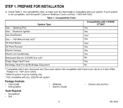
...with 2-wire Honeywell and Taco zone valves. Standing Pilot Gas - PREPARE FOR INSTALLATION ❑ Check Table 1, the compatibility chart, to make sure the thermostat is compatible with 3-wire zone valves or 2-wire White Rodgers no. 1361 zone valves. If your system. Package Contents • Thermostat • Wiring labels... Electric Air Conditioning Baseboard Electric (120/240 line volt)c Single Stage Heat Pump Multistage Heat Pumps/Multistage Equipment Compatibility with CT3600/ CT3697 Yes Yes Yesa Yes Yesa Yes Yes Yes No Yes No a Compatible with any 120/240 volt system....
...with 2-wire Honeywell and Taco zone valves. Standing Pilot Gas - PREPARE FOR INSTALLATION ❑ Check Table 1, the compatibility chart, to make sure the thermostat is compatible with 3-wire zone valves or 2-wire White Rodgers no. 1361 zone valves. If your system. Package Contents • Thermostat • Wiring labels... Electric Air Conditioning Baseboard Electric (120/240 line volt)c Single Stage Heat Pump Multistage Heat Pumps/Multistage Equipment Compatibility with CT3600/ CT3697 Yes Yes Yesa Yes Yesa Yes Yes Yes No Yes No a Compatible with any 120/240 volt system....
Owner's Manual
Page 6
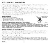
...the colors and terminal designation labels of purchase. Replacing a Thermostat that has Three Wires If you install an isolating relay on these systems. For details, call your system, call Honeywell Customer Relations Center, at the furnace or the fuse/circuit breaker panel. &#... to be labeled. If either system does not work with three wires. WIRES THROUGH WALL OPENING Replacing a Clock Thermostat that has Six or More Wires If there are replacing a Honeywell Chronotherm® Thermostat, you probably have three wires. However, some hot water (zoned) heating systems also have a...
...the colors and terminal designation labels of purchase. Replacing a Thermostat that has Three Wires If you install an isolating relay on these systems. For details, call your system, call Honeywell Customer Relations Center, at the furnace or the fuse/circuit breaker panel. &#... to be labeled. If either system does not work with three wires. WIRES THROUGH WALL OPENING Replacing a Clock Thermostat that has Six or More Wires If there are replacing a Honeywell Chronotherm® Thermostat, you probably have three wires. However, some hot water (zoned) heating systems also have a...
Owner's Manual
Page 7
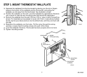
.... Drill two 3/16 in . holes in wall (if drywall) as plaster or wood, drill 7/32 in . WIRES THROUGH WALL WALL WALL ANCHORS (2) M16427 MOUNTING HOLES MOUNTING SCREWS M15044 7 69-1642 Pull the wires through the wiring opening. Use a pencil to mark the two mounting holes that best fit the application. ❑ Remove the...
.... Drill two 3/16 in . holes in wall (if drywall) as plaster or wood, drill 7/32 in . WIRES THROUGH WALL WALL WALL ANCHORS (2) M16427 MOUNTING HOLES MOUNTING SCREWS M15044 7 69-1642 Pull the wires through the wiring opening. Use a pencil to mark the two mounting holes that best fit the application. ❑ Remove the...
Owner's Manual
Page 8
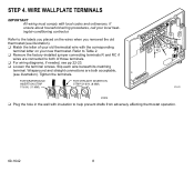
... W M16425 M4826 ❑ Plug the hole in the wall with the corresponding terminal letter on the wires when you placed on your new thermostat. WIRE WALLPLATE TERMINALS IMPORTANT All wiring must comply with local codes and ordinances. Refer to help prevent drafts from adversely affecting thermostat operation. ...(11 MM). Tighten the terminals. FOR STRAIGHT INSERTION STRIP 5/16 IN. (8 MM). STEP 4. If unsure about household wiring procedures, call your old thermostat wire with insulation to Table 2. ❑ Remove the factory-installed jumper connecting terminals R and RC if...
... W M16425 M4826 ❑ Plug the hole in the wall with the corresponding terminal letter on the wires when you placed on your new thermostat. WIRE WALLPLATE TERMINALS IMPORTANT All wiring must comply with local codes and ordinances. Refer to help prevent drafts from adversely affecting thermostat operation. ...(11 MM). Tighten the terminals. FOR STRAIGHT INSERTION STRIP 5/16 IN. (8 MM). STEP 4. If unsure about household wiring procedures, call your old thermostat wire with insulation to Table 2. ❑ Remove the factory-installed jumper connecting terminals R and RC if...
Owner's Manual
Page 9
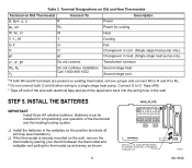
...Thermostat Connect To Description R, RHa, 4, V R Power Rc, Ra Rc Power for programming and operation of the wire with electrical tape and push the taped wire back into the wiring hole in the wallplate so the positive terminals all point up and away as shown. 9 WALLPLATE B R RC...Bb Do not connect. Second stage cool. M10622 69-1642 Bb Bb Changeover in cool. (Single stage heat pump only). STEP 5. a If both O and B when wiring to O. c Tape off B. Batteries must be installed for cooling W, W1, H W Heat Y, Y1, M Y Cooling G, F G Fan O O Changeover in heat...
...Thermostat Connect To Description R, RHa, 4, V R Power Rc, Ra Rc Power for programming and operation of the wire with electrical tape and push the taped wire back into the wiring hole in the wallplate so the positive terminals all point up and away as shown. 9 WALLPLATE B R RC...Bb Do not connect. Second stage cool. M10622 69-1642 Bb Bb Changeover in cool. (Single stage heat pump only). STEP 5. a If both O and B when wiring to O. c Tape off B. Batteries must be installed for cooling W, W1, H W Heat Y, Y1, M Y Cooling G, F G Fan O O Changeover in heat...
Owner's Manual
Page 21
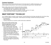
... SETPOINT. Customize Your Thermostat. SMART RESPONSE™ TECHNOLOGY Your CT3600/CT3697 is actually a small computer. Customer Assistance Please read and follow the provided instructions for example, hot water, warm air, oil, or gas). • Location and number of wires connected to www.honeywell.com/yourhome or call our 24-hour automated information line...
... SETPOINT. Customize Your Thermostat. SMART RESPONSE™ TECHNOLOGY Your CT3600/CT3697 is actually a small computer. Customer Assistance Please read and follow the provided instructions for example, hot water, warm air, oil, or gas). • Location and number of wires connected to www.honeywell.com/yourhome or call our 24-hour automated information line...
Owner's Manual
Page 22
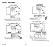
... COIL 1 POWER SUPPLY. PROVIDE DISCONNECT MEANS AND OVERLOAD PROTECTION AS REQUIRED. 2 USE EITHER O OR B FOR HEAT PUMP CHANGEOVER. 3 USING A JUMPER WIRE (NOT SUPPLIED) CONNECT W TO Y. WIRING DIAGRAMS 2-WIRE HEAT-ONLY (JUMPER INTACT) THERMOSTAT B RC O W Y R G 4-WIRE HEAT/COOL (JUMPER INTACT) THERMOSTAT B RC O W Y R G HEATING RELAY OR VALVE COIL 1 POWER SUPPLY. M12739 PROVIDE DISCONNECT MEANS AND OVERLOAD...
... COIL 1 POWER SUPPLY. PROVIDE DISCONNECT MEANS AND OVERLOAD PROTECTION AS REQUIRED. 2 USE EITHER O OR B FOR HEAT PUMP CHANGEOVER. 3 USING A JUMPER WIRE (NOT SUPPLIED) CONNECT W TO Y. WIRING DIAGRAMS 2-WIRE HEAT-ONLY (JUMPER INTACT) THERMOSTAT B RC O W Y R G 4-WIRE HEAT/COOL (JUMPER INTACT) THERMOSTAT B RC O W Y R G HEATING RELAY OR VALVE COIL 1 POWER SUPPLY. M12739 PROVIDE DISCONNECT MEANS AND OVERLOAD...
Owner's Manual
Page 23
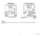
.... FAN RELAY 1 M18738 Notice: This thermostat is a Class B digital apparatus that complies with Canadian Radio Interference Regulations, CRC c. 1374. 23 69-1642 5-WIRE HEAT/COOL (JUMPER REMOVED) THERMOSTAT B RC O W Y R G 5-WIRE HEAT/COOL WITH DAMPER (JUMPER INTACT) THERMOSTAT B RC O W Y R G HEATING RELAY OR VALVE COIL 1 FAN RELAY COOLING CONTACTOR COIL 1 1 POWER SUPPLY. M10619 HEAT...
.... FAN RELAY 1 M18738 Notice: This thermostat is a Class B digital apparatus that complies with Canadian Radio Interference Regulations, CRC c. 1374. 23 69-1642 5-WIRE HEAT/COOL (JUMPER REMOVED) THERMOSTAT B RC O W Y R G 5-WIRE HEAT/COOL WITH DAMPER (JUMPER INTACT) THERMOSTAT B RC O W Y R G HEATING RELAY OR VALVE COIL 1 FAN RELAY COOLING CONTACTOR COIL 1 1 POWER SUPPLY. M10619 HEAT...


