

User Manual
Page 4
...; Shut off balance. ■ When cutting a limb that is under tension, be struck when the tension in the wood fibers is damaged, improperly adjusted, or not completely and securely assembled. this section of the operator's manual are very hot during and after operation of less than the items listed...
...; Shut off balance. ■ When cutting a limb that is under tension, be struck when the tension in the wood fibers is damaged, improperly adjusted, or not completely and securely assembled. this section of the operator's manual are very hot during and after operation of less than the items listed...
User Manual
Page 5
... Carburetor in the user's hands due to vibration. Prolonged periods of cut-resistant material or ones that is damaged, improperly adjusted, or is not completely and securely assembled. It is highly flammable. ■ Mix and store fuel in a container approved for gasoline. ■... as well as clearing, pruning, cutting firewood, etc. Do not wear loose fitting clothing, which could be appropriate to use , it may need adjusting. Secure hair so that the saw chain stops moving when the throttle control trigger is released. NOTE: The size of the work area depends on...
... Carburetor in the user's hands due to vibration. Prolonged periods of cut-resistant material or ones that is damaged, improperly adjusted, or is not completely and securely assembled. It is highly flammable. ■ Mix and store fuel in a container approved for gasoline. ■... as well as clearing, pruning, cutting firewood, etc. Do not wear loose fitting clothing, which could be appropriate to use , it may need adjusting. Secure hair so that the saw chain stops moving when the throttle control trigger is released. NOTE: The size of the work area depends on...
User Manual
Page 16
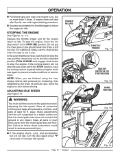
...event that the chain/guide bar does not contact the ground or any object. ADJUSTING IDLE SPEED See Figure 14. Wear all protective clothing and keep all parts of ...saw when set the chain brake when the saw on / stop the engine, move around the guide bar when adjusting the idle speed. For additional safety, set to the STOP position, have the on/stop switch repaired before ...storing. If the on /stop switch will not stop the engine. Make adjustments with the unit supported on a stable surface so that the on /stop switch will not stop the saw, ...
...event that the chain/guide bar does not contact the ground or any object. ADJUSTING IDLE SPEED See Figure 14. Wear all protective clothing and keep all parts of ...saw when set the chain brake when the saw on / stop the engine, move around the guide bar when adjusting the idle speed. For additional safety, set to the STOP position, have the on/stop switch repaired before ...storing. If the on /stop switch will not stop the engine. Make adjustments with the unit supported on a stable surface so that the on /stop switch will not stop the saw, ...

User Manual
Page 17
... the guide bar up and back toward the operator. PUSH Fig. 15 WARNING: KICKBACK occurs when the moving . See General Safety Rules for adjustment and discontinue use until the repair is made . English PULL PULL AND PUSH See Figure 15. If the saw chain is moving chain contacts ... at idle, turn the idle speed screw "T" counterclockwise to reduce the idle RPM and stop the chain, or contact an authorized service center for adjustment and discontinue use until the repair is made . Turn the idle speed screw "T" counterclockwise to control the PULL when cutting on the saw . Thus...
... the guide bar up and back toward the operator. PUSH Fig. 15 WARNING: KICKBACK occurs when the moving . See General Safety Rules for adjustment and discontinue use until the repair is made . English PULL PULL AND PUSH See Figure 15. If the saw chain is moving chain contacts ... at idle, turn the idle speed screw "T" counterclockwise to reduce the idle RPM and stop the chain, or contact an authorized service center for adjustment and discontinue use until the repair is made . Turn the idle speed screw "T" counterclockwise to control the PULL when cutting on the saw . Thus...
User Manual
Page 26
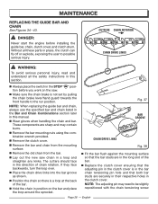
... in this manual. The cutters should face in place, the clutch can fly off or explode, exposing the user to possible serious injury. NOTE: The adjusting pin may contain burrs. n Remove the bar mounting nuts using the combination wrench provided. n Lay out the new saw . If they face backwards, ...specified bar and chain listed in the Bar and Chain Combinations section later in the clutch cover. n Replace the clutch cover ensuring that the adjusting pin in the clutch cover is not set by pulling the chain brake lever/hand guard towards the front handle to be slightly repositioned with...
... in this manual. The cutters should face in place, the clutch can fly off or explode, exposing the user to possible serious injury. NOTE: The adjusting pin may contain burrs. n Remove the bar mounting nuts using the combination wrench provided. n Lay out the new saw . If they face backwards, ...specified bar and chain listed in the Bar and Chain Combinations section later in the clutch cover. n Replace the clutch cover ensuring that the adjusting pin in the clutch cover is not set by pulling the chain brake lever/hand guard towards the front handle to be slightly repositioned with...
User Manual
Page 27
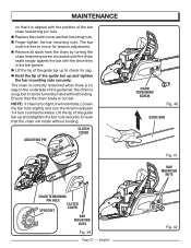
... on the underside of the guide bar, the chain is snug, but it can be free to check for tension adjustment. Loosen the bar nuts slightly and turn the tension adjuster 1/4 turn counterclockwise. Ensure that it will rotate without binding. Ensure that the chain will not rotate. n Remove all... the chain seats snugly against the bar with the position of the guide bar up and tighten the bar mounting nuts securely. CLUTCH COVER ADJUSTING PIN CHAIN TENSIONING SCREW Fig. 40 GUIDE BAR Fig. 41 BAR MOUNTING NUTS CHAIN TENSIONING PIN HOLE CLUTCH COVER SPROCKET BAR MOUNTING NUTS Fig...
... on the underside of the guide bar, the chain is snug, but it can be free to check for tension adjustment. Loosen the bar nuts slightly and turn the tension adjuster 1/4 turn counterclockwise. Ensure that it will rotate without binding. Ensure that the chain will not rotate. n Remove all... the chain seats snugly against the bar with the position of the guide bar up and tighten the bar mounting nuts securely. CLUTCH COVER ADJUSTING PIN CHAIN TENSIONING SCREW Fig. 40 GUIDE BAR Fig. 41 BAR MOUNTING NUTS CHAIN TENSIONING PIN HOLE CLUTCH COVER SPROCKET BAR MOUNTING NUTS Fig...
User Manual
Page 28
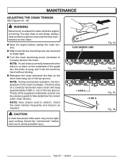
...to finger tight. CAUTION: A chain tensioned while warm may be used as required. Check the "cold tension" before setting the chain tension. MAINTENANCE ADJUSTING THE CHAIN TENSION See Figures 44 - 46. NOTE: During normal saw chain is no slack on the underside of a correctly tensioned warm chain ...chain tension frequently and tension as a guide to stretch; The saw operation, the temperature of the bar groove. English WARNING: Never touch or adjust the chain while the engine is snug, and it can be too tight upon cooling. NOTE: New chains tend to help determine the correct...
...to finger tight. CAUTION: A chain tensioned while warm may be used as required. Check the "cold tension" before setting the chain tension. MAINTENANCE ADJUSTING THE CHAIN TENSION See Figures 44 - 46. NOTE: During normal saw chain is no slack on the underside of a correctly tensioned warm chain ...chain tension frequently and tension as a guide to stretch; The saw operation, the temperature of the bar groove. English WARNING: Never touch or adjust the chain while the engine is snug, and it can be too tight upon cooling. NOTE: New chains tend to help determine the correct...
User Manual
Page 30
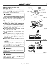
... file the right hand cutters in . n Use a 5/32 in the opposite direction. Do not let the file dip or rock. n Tension the chain prior to Adjusting The Chain Tension. English MAINTENANCE SHARPENING THE CUTTERS See Figures 49 - 52. n Lift the file away from the file with the top plate of the...
... file the right hand cutters in . n Use a 5/32 in the opposite direction. Do not let the file dip or rock. n Tension the chain prior to Adjusting The Chain Tension. English MAINTENANCE SHARPENING THE CUTTERS See Figures 49 - 52. n Lift the file away from the file with the top plate of the...
User Manual
Page 31
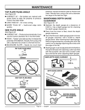
... not to damage adjoining drive links with the edge of the file. ■n Depth gauges must be adjusted with the flat file in the same direction the adjoining cutter was filed with flat file when adjusting depth gauges. After lowering each depth gauge, restore original shape by rounding the front. CORRECT LESS...
... not to damage adjoining drive links with the edge of the file. ■n Depth gauges must be adjusted with the flat file in the same direction the adjoining cutter was filed with flat file when adjusting depth gauges. After lowering each depth gauge, restore original shape by rounding the front. CORRECT LESS...
User Manual
Page 33
These are specially hardened screws. In addition to 45 in warm soapy water, rinse, and let dry completely. wrench (or adjustable wrench) to achieve the recommended torque of the bar, the SAFE-T-TIP® also helps keep the carburetor from abrasive surfaces, such as much loose ...
These are specially hardened screws. In addition to 45 in warm soapy water, rinse, and let dry completely. wrench (or adjustable wrench) to achieve the recommended torque of the bar, the SAFE-T-TIP® also helps keep the carburetor from abrasive surfaces, such as much loose ...
User Manual
Page 34
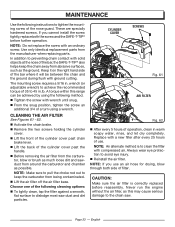
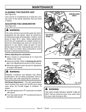
...children, and pets at idle. Refer to increase idle speed. MAINTENANCE CLEANING THE STARTER UNIT See Figure 63. ter in serious personal injury. To adjust: n Turn idle speed screw "T" clockwise to Cleaning the Air Fil- IDLE SPEED SCREW "T" STARTER COVER VENTS Fig. 63 CYLINDER COVER SCREWS Fig... all protective clothing and keep the cooling vents of the starter assembly free and clean of your body away from the saw while adjusting the carburetor. Before adjusting the carburetor: n Use a brush or compressed air to the chain saw chain turning at least 50 ft. n Clean the ...
...children, and pets at idle. Refer to increase idle speed. MAINTENANCE CLEANING THE STARTER UNIT See Figure 63. ter in serious personal injury. To adjust: n Turn idle speed screw "T" clockwise to Cleaning the Air Fil- IDLE SPEED SCREW "T" STARTER COVER VENTS Fig. 63 CYLINDER COVER SCREWS Fig... all protective clothing and keep the cooling vents of the starter assembly free and clean of your body away from the saw while adjusting the carburetor. Before adjusting the carburetor: n Use a brush or compressed air to the chain saw chain turning at least 50 ft. n Clean the ...
User Manual
Page 37
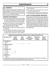
Keep away from carburetor. When storing 1 month or longer: n Drain all foreign material from the product. An engine adjusted for oil. In doing so, the engine will remove all fuel-lubricant mix that is to perform under field conditions cannot be run at ... poor engine performance and increased emissions. MAINTENANCE WARNING: Even with daily cleaning of the mechanism, the dependability of gasoline. Please have an authorized service center adjust this engine if it stops. Keep the SAFE-T-TIP® nose guard on the saw's guide bar and use proper cutting techniques. n Abide by ...
Keep away from carburetor. When storing 1 month or longer: n Drain all foreign material from the product. An engine adjusted for oil. In doing so, the engine will remove all fuel-lubricant mix that is to perform under field conditions cannot be run at ... poor engine performance and increased emissions. MAINTENANCE WARNING: Even with daily cleaning of the mechanism, the dependability of gasoline. Please have an authorized service center adjust this engine if it stops. Keep the SAFE-T-TIP® nose guard on the saw's guide bar and use proper cutting techniques. n Abide by ...
User Manual
Page 38
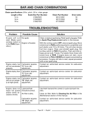
... Page 38 - chain gauge Length of this manual. Contact an authorized service center for carburetor adjustment. Contact an authorized service center for carburetor adjustment. English "L" (Low Jet) adjustment. Engine starts but Carburetor requires will clear excess fuel from engine. If engine still fails to...CHOKE and repeat normal starting procedure. Engine starts, then Carburetor requires dies. Contact an authorized service center for carburetor adjustment. "H" (High Jet) ly at RUN. Clean and reinstall spark plug. Move choke lever to RUN position ...
... Page 38 - chain gauge Length of this manual. Contact an authorized service center for carburetor adjustment. Contact an authorized service center for carburetor adjustment. English "L" (Low Jet) adjustment. Engine starts but Carburetor requires will clear excess fuel from engine. If engine still fails to...CHOKE and repeat normal starting procedure. Engine starts, then Carburetor requires dies. Contact an authorized service center for carburetor adjustment. "H" (High Jet) ly at RUN. Clean and reinstall spark plug. Move choke lever to RUN position ...
User Manual
Page 39
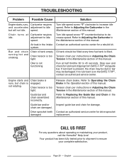
...assembled incorrectly. Turn idle speed screw "T" clockwise to idle speed. Air leak in the Maintenance section of this manual. Refer to Adjusting the Carburetor in the Maintenance section of this manual. Engine starts and runs, but will not idle. Drive sprocket teeth ...chain brake. Your product has been fully tested prior to shipment to Adjusting the Carburetor in the intake Contact an authorized service center for drive sprocket replacement. 1-800-242-4672 CALL www.homelite.com CALL US FIRST For any questions about operating or maintaining your ...
...assembled incorrectly. Turn idle speed screw "T" clockwise to idle speed. Air leak in the Maintenance section of this manual. Refer to Adjusting the Carburetor in the Maintenance section of this manual. Engine starts and runs, but will not idle. Drive sprocket teeth ...chain brake. Your product has been fully tested prior to shipment to Adjusting the Carburetor in the intake Contact an authorized service center for drive sprocket replacement. 1-800-242-4672 CALL www.homelite.com CALL US FIRST For any questions about operating or maintaining your ...
User Manual
Page 40
... or replacements and no claim of breach of original retail purchase for any HOMELITE brand product that is limited to ninety (90) days from state to state. Spark Plugs, Carburetor, Carburetor Adjustments, Ignition, Filters B. Page 40 - English ALL IMPLIED WARRANTIES ARE LIMITED... IN DURATION TO THE STATED WARRANTY PERIOD. This warranty does not cover any HOMELITE brand product that has been subject to misuse, neglect, negligence...
... or replacements and no claim of breach of original retail purchase for any HOMELITE brand product that is limited to ninety (90) days from state to state. Spark Plugs, Carburetor, Carburetor Adjustments, Ignition, Filters B. Page 40 - English ALL IMPLIED WARRANTIES ARE LIMITED... IN DURATION TO THE STATED WARRANTY PERIOD. This warranty does not cover any HOMELITE brand product that has been subject to misuse, neglect, negligence...
User Manual 2
Page 4
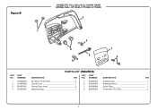
Figure B HOMELITE 35cc/38cc/42cc CHAIN SAWS MODEL NOs. UT10548, UT10568, UT10588 2 1 4 3 6 5 7 8 KEY NO. 1 2 3 4 PARTS LIST (FIGURE B) PART NUMBER DESCRIPTION QTY KEY PART NO. NUMBER DESCRIPTION QTY 678339003 Nut (5/16-18, Hex Hd 2 518858002 Clutch Cover 1 678621001 Clutch Cover Insert 2 610624001 Adjusting Gear 1 5 678327001 Adjusting Nut 1 6 610623001 Adjusting Screw 1 7 638298001 Guide Plate 1 8 660922001 Screw (M4, Torx T20 2 4
Figure B HOMELITE 35cc/38cc/42cc CHAIN SAWS MODEL NOs. UT10548, UT10568, UT10588 2 1 4 3 6 5 7 8 KEY NO. 1 2 3 4 PARTS LIST (FIGURE B) PART NUMBER DESCRIPTION QTY KEY PART NO. NUMBER DESCRIPTION QTY 678339003 Nut (5/16-18, Hex Hd 2 518858002 Clutch Cover 1 678621001 Clutch Cover Insert 2 610624001 Adjusting Gear 1 5 678327001 Adjusting Nut 1 6 610623001 Adjusting Screw 1 7 638298001 Guide Plate 1 8 660922001 Screw (M4, Torx T20 2 4

