
Specifications
Page 5
... 41 6.4 Environment 45 6.4.1 Temperature and humidity 45 6.4.2 Corrosion test 46 6.5 DC power requirements 47 Deskstar 180GXP hard disk drive specifications v Functional specification 5 3.0 Fixed disk subsystem description 7 3.1 Control Electronics 7 3.2 Head disk assembly 7 3.3 Actuator 7 4.0 Drive characteristics 9 4.1 Default logical drive parameters 9 4.2 Data sheet 10 4.3 Drive organization 11 4.3.1 Drive format 11 4.3.2 Cylinder allocation 11 4.4 Performance characteristics 12 4.4.1 Command overhead 12 4.4.2 Mechanical positioning...
... 41 6.4 Environment 45 6.4.1 Temperature and humidity 45 6.4.2 Corrosion test 46 6.5 DC power requirements 47 Deskstar 180GXP hard disk drive specifications v Functional specification 5 3.0 Fixed disk subsystem description 7 3.1 Control Electronics 7 3.2 Head disk assembly 7 3.3 Actuator 7 4.0 Drive characteristics 9 4.1 Default logical drive parameters 9 4.2 Data sheet 10 4.3 Drive organization 11 4.3.1 Drive format 11 4.3.2 Cylinder allocation 11 4.4 Performance characteristics 12 4.4.1 Command overhead 12 4.4.2 Mechanical positioning...

Specifications
Page 6
... 59 6.11.4 Safe handling 59 6.11.5 Environment 59 6.11.6 Secondary circuit protection 59 6.12 Electromagnetic compatibility 60 6.12.1 CE Mark 60 6.12.2 C-Tick Mark 60 Part 2. Interface specification 61 7.0 General 63 7.1 Terminology 63 7.2 Deviations from standard 63 8.0 Registers 65 8.1... Register 67 8.6 Device Control Register 67 8.7 Drive Address Register 67 8.8 Device/Head Register 68 8.9 Error Register 68 8.10 Features Register 69 8.11 Sector Count Register 69 8.12 Sector Number Register 69 8.13 Status Register 70 Deskstar 180GXP hard disk drive specifications vi
... 59 6.11.4 Safe handling 59 6.11.5 Environment 59 6.11.6 Secondary circuit protection 59 6.12 Electromagnetic compatibility 60 6.12.1 CE Mark 60 6.12.2 C-Tick Mark 60 Part 2. Interface specification 61 7.0 General 63 7.1 Terminology 63 7.2 Deviations from standard 63 8.0 Registers 65 8.1... Register 67 8.6 Device Control Register 67 8.7 Drive Address Register 67 8.8 Device/Head Register 68 8.9 Error Register 68 8.10 Features Register 69 8.11 Sector Count Register 69 8.12 Sector Number Register 69 8.13 Status Register 70 Deskstar 180GXP hard disk drive specifications vi
Specifications
Page 11
... chart (Device Pausing Write 35 Figure 38. and 3-disk model shown 39 Figure 45. Jumper positions for Ultra DMA 22 Figure 21. Head switch time 13 Figure 8. Random Access Performance 16 Figure 15. Ultra DMA cycle timing chart (Initiating Read 30 Figure 28. Ultra DMA ...13 Figure 7. Data transfer speed 15 Figure 13. Power connector pin assignments 21 Figure 19. Table of temperature and humidity 46 Deskstar 180GXP hard disk drive specifications xi Signal special definitions for capacity clip to 2GB/32GB 43 Figure 50. Jumper pin assignment 40 Figure 47. Latency ...
... chart (Device Pausing Write 35 Figure 38. and 3-disk model shown 39 Figure 45. Jumper positions for Ultra DMA 22 Figure 21. Head switch time 13 Figure 8. Random Access Performance 16 Figure 15. Ultra DMA cycle timing chart (Initiating Read 30 Figure 28. Ultra DMA ...13 Figure 7. Data transfer speed 15 Figure 13. Power connector pin assignments 21 Figure 19. Table of temperature and humidity 46 Deskstar 180GXP hard disk drive specifications xi Signal special definitions for capacity clip to 2GB/32GB 43 Figure 50. Jumper pin assignment 40 Figure 47. Latency ...
Specifications
Page 12
...(EAh 116 Figure 98. Identify Device Information (part 6 of 60 GB, 40GB, and 30 GB models 48 Figure 57. Power supply current of 6 126 Figure...part 5 of 6 122 Figure 103. Idle Command (E3h/97h 127 Deskstar 180GXP hard disk drive specifications xii Alternate Status Register 66 Figure 70. DCO error information definition 113...drive power connector 49 Figure 58. Command set (1 of 6 124 Figure 105. Power supply current of 2 84 Figure 84. Command table for device lock operation (part 2 of 6 123 Figure 104. Reset Response Table 71 Figure 76. Device/Head...
...(EAh 116 Figure 98. Identify Device Information (part 6 of 60 GB, 40GB, and 30 GB models 48 Figure 57. Power supply current of 6 126 Figure...part 5 of 6 122 Figure 103. Idle Command (E3h/97h 127 Deskstar 180GXP hard disk drive specifications xii Alternate Status Register 66 Figure 70. DCO error information definition 113...drive power connector 49 Figure 58. Command set (1 of 6 124 Figure 105. Power supply current of 2 84 Figure 84. Command table for device lock operation (part 2 of 6 123 Figure 104. Reset Response Table 71 Figure 76. Device/Head...

Specifications
Page 21
... starting, stopping, and monitoring of the actuator. The actuator assembly is assembled in a desired position. y Monitors various timers such as head settle and servo failure. A closed loop control. Deskstar 180GXP hard disk drive specifications 7 y Analyzes servo signals to allow vertical or horizontal mounting without adjustment. y Controls the voice coil motor driver to keep the...
... starting, stopping, and monitoring of the actuator. The actuator assembly is assembled in a desired position. y Monitors various timers such as head settle and servo failure. A closed loop control. Deskstar 180GXP hard disk drive specifications 7 y Analyzes servo signals to allow vertical or horizontal mounting without adjustment. y Controls the voice coil motor driver to keep the...

Specifications
Page 23
...default setting can be obtained by issuing an IDENTIFY DEVICE command Deskstar 180GXP hard disk drive specifications 9 The Logical layout to access the drive from the system interface. Description IC35L030AVV207 IC35L060AVV207 IC35L060AVV207 Optimized 40 GB Physical Layout Label capacity (GB) 30 40 40 Bytes per Sector 512 512 512 Sectors...880 41,174,138,880 IC35L060AVV207 60 512 536-1092 2 1 1072-2184 857-4481 16 63 16,383 120,103,200 61,492,838,400 Description Physical Layout Label capacity (GB) Bytes per Sector Sectors per Track Number of Heads Number of Disks Data ...
...default setting can be obtained by issuing an IDENTIFY DEVICE command Deskstar 180GXP hard disk drive specifications 9 The Logical layout to access the drive from the system interface. Description IC35L030AVV207 IC35L060AVV207 IC35L060AVV207 Optimized 40 GB Physical Layout Label capacity (GB) 30 40 40 Bytes per Sector 512 512 512 Sectors...880 41,174,138,880 IC35L060AVV207 60 512 536-1092 2 1 1072-2184 857-4481 16 63 16,383 120,103,200 61,492,838,400 Description Physical Layout Label capacity (GB) Bytes per Sector Sectors per Track Number of Heads Number of Disks Data ...

Specifications
Page 27
... seek time Full stroke seek is not used throughout this specification with a random head switch from the start of the motion of the actuator to complete a seek... seek (without command overhead, including settling) Function Read (80 GB - 180 GB models) Read (30 GB & 60 GB models) Write (80 GB - 180 GB models) Write (30 GB & 60 GB models) Read (Quiet Seek mode) Write (Quiet Seek mode)...drive population tested at nominal environmental and voltage conditions. max. Σ (max. + 1 - The average of a reliable read or write operation. Deskstar 180GXP hard disk drive specifications 13
... seek time Full stroke seek is not used throughout this specification with a random head switch from the start of the motion of the actuator to complete a seek... seek (without command overhead, including settling) Function Read (80 GB - 180 GB models) Read (30 GB & 60 GB models) Write (80 GB - 180 GB models) Write (30 GB & 60 GB models) Read (Quiet Seek mode) Write (Quiet Seek mode)...drive population tested at nominal environmental and voltage conditions. max. Σ (max. + 1 - The average of a reliable read or write operation. Deskstar 180GXP hard disk drive specifications 13

Specifications
Page 28
... GB models Typical (sec) 6 8 10 Maximum (sec) 31 31 31 Figure 11. Single Track Seek Time Single track seek is given in both directions (inward and outward). 4.4.2.6 Average latency Rotational speed 7200 RPM Time for a revolution (ms) 8.3 Figure 10. 4.4.2.4 Cylinder switch time (Cylinder skew) 72 kTPI Cylinder switch time - Deskstar 180GXP hard disk drive...
... GB models Typical (sec) 6 8 10 Maximum (sec) 31 31 31 Figure 11. Single Track Seek Time Single track seek is given in both directions (inward and outward). 4.4.2.6 Average latency Rotational speed 7200 RPM Time for a revolution (ms) 8.3 Figure 10. 4.4.2.4 Cylinder switch time (Cylinder skew) 72 kTPI Cylinder switch time - Deskstar 180GXP hard disk drive...

Specifications
Page 29
...Deskstar 180GXP hard disk drive specifications 15 read typical Buffer-Host (max) 180 GB model (Mbyte/s) 66 56.3 34.5 29.4 100 Figure 12. Data transfer speed y Instantaneous disk-buffer transfer rate (Mbyte/s) is defined by the following formula: (Sustained Transfer Rate) = A / (B +C +D ) where A = 512 (number of data sectors per cylinder - 1) (head... typical Disk-Buffer transfer (Zone 26) Instantaneous - y Sustained disk-buffer transfer rate (Mbyte/s) is derived by considering head/cylinder change time D = (number of the host. It is given in 4.4.5, "Throughput" on the speed of ...
...Deskstar 180GXP hard disk drive specifications 15 read typical Buffer-Host (max) 180 GB model (Mbyte/s) 66 56.3 34.5 29.4 100 Figure 12. Data transfer speed y Instantaneous disk-buffer transfer rate (Mbyte/s) is defined by the following formula: (Sustained Transfer Rate) = A / (B +C +D ) where A = 512 (number of data sectors per cylinder - 1) (head... typical Disk-Buffer transfer (Zone 26) Instantaneous - y Sustained disk-buffer transfer rate (Mbyte/s) is derived by considering head/cylinder change time D = (number of the host. It is given in 4.4.5, "Throughput" on the speed of ...

Specifications
Page 31
... an actual spin down Seek operation mode Write operation mode Read operation mode Spindle rotation at 7200 RPM with heads unloaded Spindle motor and servo system are shown below. Mode transition times Deskstar 180GXP hard disk drive specifications 17 Commands can be received immediately Actuator is unloaded and spindle motor is stopped. Figure 15.
... an actual spin down Seek operation mode Write operation mode Read operation mode Spindle rotation at 7200 RPM with heads unloaded Spindle motor and servo system are shown below. Mode transition times Deskstar 180GXP hard disk drive specifications 17 Commands can be received immediately Actuator is unloaded and spindle motor is stopped. Figure 15.

Specifications
Page 37
...Error {Features when written}, Sector Count, Sector Number, Cylinder Low, Cylinder High, Drive/Head and Status {Command when written} register) can be unable to a register or data register of the drive onto data bus. CS1RESETDIOW- When active, one of an 80-conductor cable assembly.... assert DASP- shall be negated following a power on the rising edge of a valid Execute Drive Diagnostics command, device 1 shall negate PDIAG- CSEL (Cable Select) (Optional) Deskstar 180GXP hard disk drive specifications 23 DA0-DA2 CS0- shall be asserted by device 1. PDIAG- If device 1 did...
...Error {Features when written}, Sector Count, Sector Number, Cylinder Low, Cylinder High, Drive/Head and Status {Command when written} register) can be unable to a register or data register of the drive onto data bus. CS1RESETDIOW- When active, one of an 80-conductor cable assembly.... assert DASP- shall be negated following a power on the rising edge of a valid Execute Drive Diagnostics command, device 1 shall negate PDIAG- CSEL (Cable Select) (Optional) Deskstar 180GXP hard disk drive specifications 23 DA0-DA2 CS0- shall be asserted by device 1. PDIAG- If device 1 did...

Specifications
Page 52
Two chip select lines (CS0- CS0- Drive/Head Reg. 1 Status Reg. For example, the host is not supposed to read status register contents before interrupt (the value is provided at the specified time. Deskstar 180GXP hard disk drive specifications 38 The CS0- while the CS1- CS1- DA2 0 1 0 0 1 0 0 1 0 0 1 0 0 1 1 0 1 1 0 1 1 0 1 1 1 0 1 DA1 0 0 1 1 0 0 1 1 1 DA0 DIOR- = 0 (Read) DIOW- = 0 (Write) Command Block Registers...
Two chip select lines (CS0- CS0- Drive/Head Reg. 1 Status Reg. For example, the host is not supposed to read status register contents before interrupt (the value is provided at the specified time. Deskstar 180GXP hard disk drive specifications 38 The CS0- while the CS1- CS1- DA2 0 1 0 0 1 0 0 1 0 0 1 0 0 1 1 0 1 1 0 1 1 0 1 1 1 0 1 DA1 0 0 1 1 0 0 1 1 1 DA0 DIOR- = 0 (Read) DIOW- = 0 (Write) Command Block Registers...

Specifications
Page 54
...for a slave device that does not comply with the ATA specification. Jumper pin assignment Deskstar 180GXP hard disk drive specifications 40 Note: In conventional terminology "Device 0" designates a Master and "Device 1"... designates a Slave. RSV GND GND GND RSV I GECA HFDB DS CS/SP GND RS V Figure 46. 6.3.3 Jumper pin assignment There are four jumper settings as shown in the following sections: y 16 logical head default (normal use) y 15 logical head default y 2 GB...
...for a slave device that does not comply with the ATA specification. Jumper pin assignment Deskstar 180GXP hard disk drive specifications 40 Note: In conventional terminology "Device 0" designates a Master and "Device 1"... designates a Slave. RSV GND GND GND RSV I GECA HFDB DS CS/SP GND RS V Figure 46. 6.3.3 Jumper pin assignment There are four jumper settings as shown in the following sections: y 16 logical head default (normal use) y 15 logical head default y 2 GB...

Specifications
Page 55
...) Present Shipping Default Condition (DEVICE 0) Figure 47. y When CSEL is open or at E-F. Deskstar 180GXP hard disk drive specifications 41 Jumper positions for normal use ) The figure below shows the jumper positions used to select... Device 0, Device 1, Cable Selection, or Device 1 (Slave) Present. 6.3.4 Jumper positions 6.3.4.1 16 logical head default (normal use Notes: 1. The shipping default position is 1 (Device 1). 2. In the CSEL mode the drive...
...) Present Shipping Default Condition (DEVICE 0) Figure 47. y When CSEL is open or at E-F. Deskstar 180GXP hard disk drive specifications 41 Jumper positions for normal use ) The figure below shows the jumper positions used to select... Device 0, Device 1, Cable Selection, or Device 1 (Slave) Present. 6.3.4 Jumper positions 6.3.4.1 16 logical head default (normal use Notes: 1. The shipping default position is 1 (Device 1). 2. In the CSEL mode the drive...

Specifications
Page 56
... B-D position does not affect any selection of default 16 logical head models. I GECA HFDB DEVICE 0 (Master) I GECA HF DB DEVICE 1 (Slave) IGECA HFDB CABLE SEL I GECA HFDB DEVICE 1 (Slave) Present Figure 48. Deskstar 180GXP hard disk drive specifications 42 In the CSEL mode, the drive address is determined by AT interface signal #28 CSEL as...
... B-D position does not affect any selection of default 16 logical head models. I GECA HFDB DEVICE 0 (Master) I GECA HF DB DEVICE 1 (Slave) IGECA HFDB CABLE SEL I GECA HFDB DEVICE 1 (Slave) Present Figure 48. Deskstar 180GXP hard disk drive specifications 42 In the CSEL mode, the drive address is determined by AT interface signal #28 CSEL as...

Specifications
Page 68
... to prevent excessive motion or vibration of the head actuator will secure the heads in all axes (6 directions). Connector locations 6.7.4 Drive mounting The drive will stay within specification limits if the drive is operated in the system securely enough to the table using ... screws. 6.7.5 Heads unload and actuator lock Heads are to be mounted in the other orientations from which it was formatted. The recommended mounting screw torque is 4 mm maximum for bottom and 4.5 mm maximum for horizontal mounting. Deskstar 180GXP hard disk drive specifications 54 Performance...
... to prevent excessive motion or vibration of the head actuator will secure the heads in all axes (6 directions). Connector locations 6.7.4 Drive mounting The drive will stay within specification limits if the drive is operated in the system securely enough to the table using ... screws. 6.7.5 Heads unload and actuator lock Heads are to be mounted in the other orientations from which it was formatted. The recommended mounting screw torque is 4 mm maximum for bottom and 4.5 mm maximum for horizontal mounting. Deskstar 180GXP hard disk drive specifications 54 Performance...

Specifications
Page 79
... Cylinder Low LBA bits 8-151 Cylinder High LBA bits 16-231 Device/Head LBA bits 24-271 Command AAxxx Invalid address 1 Mapping of registers in LBA mode Logic conventions: A = signal asserted N = signal negated X = may be A or N Figure 68. Deskstar 180GXP hard disk drive specifications 65 The Control Block Registers are used Command block registers...
... Cylinder Low LBA bits 8-151 Cylinder High LBA bits 16-231 Device/Head LBA bits 24-271 Command AAxxx Invalid address 1 Mapping of registers in LBA mode Logic conventions: A = signal asserted N = signal negated X = may be A or N Figure 68. Deskstar 180GXP hard disk drive specifications 65 The Control Block Registers are used Command block registers...

Specifications
Page 81
...when DRQ=1 in a high impedance state. -WTG -Write Gate. Setting RST=0 re-enables the device. Drive Address Register This register contains the inverted drive select and head select addresses of the currently selected drive. This bit is transferred on a Format Track command and configuration information is zero when writing to zero. ...Status Register. 8.6 Device Control Register Device Control Register 7 6 5 4 3 2 1 0 HOB - - - 1 SRST -IEN 0 Figure 70. When -IEN=1 or the device is held reset when RST=1. Deskstar 180GXP hard disk drive specifications 67
...when DRQ=1 in a high impedance state. -WTG -Write Gate. Setting RST=0 re-enables the device. Drive Address Register This register contains the inverted drive select and head select addresses of the currently selected drive. This bit is transferred on a Format Track command and configuration information is zero when writing to zero. ...Status Register. 8.6 Device Control Register Device Control Register 7 6 5 4 3 2 1 0 HOB - - - 1 SRST -IEN 0 Figure 70. When -IEN=1 or the device is held reset when RST=1. Deskstar 180GXP hard disk drive specifications 67

Specifications
Page 82
... a diagnostic code. When DRV=0, device 0 (master) is selected and active. -DS0 -Drive Select 0. except Execute Device Diagnostic - Deskstar 180GXP hard disk drive specifications 68 -H3,-H2,-H1,-H0 -Head Select. DS1=0 when device 1 (slave) is selected. Device/Head Register This register contains the device and head numbers. Bit Definitions L Binary encoded address mode select. DRV Device. When...
... a diagnostic code. When DRV=0, device 0 (master) is selected and active. -DS0 -Drive Select 0. except Execute Device Diagnostic - Deskstar 180GXP hard disk drive specifications 68 -H3,-H2,-H1,-H0 -Head Select. DS1=0 when device 1 (slave) is selected. Device/Head Register This register contains the device and head numbers. Bit Definitions L Binary encoded address mode select. DRV Device. When...
Specifications
Page 84
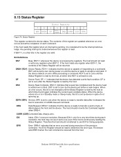
... the device is settled over a track. DSC=1 indicates that the device has detected a write fault condition. SERV (SRV) Service. Always zero. Deskstar 180GXP hard disk drive specifications 70 Any pending interrupt is cleared whenever this bit is not changed until the Status Register is read by the host, at which... completion of not spinning up. If the host reads any registers when BSY=1. DF = 1 indicates that a seek has completed and the device head is ready to zero by device in spite of each revolution, the host may not see it set back to zero until the Status Register...
... the device is settled over a track. DSC=1 indicates that the device has detected a write fault condition. SERV (SRV) Service. Always zero. Deskstar 180GXP hard disk drive specifications 70 Any pending interrupt is cleared whenever this bit is not changed until the Status Register is read by the host, at which... completion of not spinning up. If the host reads any registers when BSY=1. DF = 1 indicates that a seek has completed and the device head is ready to zero by device in spite of each revolution, the host may not see it set back to zero until the Status Register...