Instruction Manual
Page 5
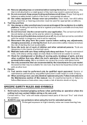
... Instruction may lead to control. (7) Check for misalignment or binding of moving parts, breakage of parts, and any adjustments, changing accessories, or storing the tool. Contact with care. Prolonged exposure to a stable platform. Keep proper footing and balance at the rate ... or other untrained persons. SPECIFIC SAFETY RULES AND SYMBOLS 1. Any tool that may become hazardous when used for your application. Accessories that are dangerous in the Maintenance section of this manual. Tools are recommended by qualified repair personnel. Follow instructions in the ...
... Instruction may lead to control. (7) Check for misalignment or binding of moving parts, breakage of parts, and any adjustments, changing accessories, or storing the tool. Contact with care. Prolonged exposure to a stable platform. Keep proper footing and balance at the rate ... or other untrained persons. SPECIFIC SAFETY RULES AND SYMBOLS 1. Any tool that may become hazardous when used for your application. Accessories that are dangerous in the Maintenance section of this manual. Tools are recommended by qualified repair personnel. Follow instructions in the ...
Instruction Manual
Page 10
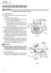
.... 2 Lever Loosen Tighten 23mm Wrench Bit Collet Chuck 16mm Wrench Fig. 3 10 Installing bits (1) Remove the motor housing from base as the standard accessory. CAUTION: ⅷ Ensure that the collet chuck is disengaged from the groove in damage to the collet chuck. 2. English INSTALLING AND ...from under the router). (Fig. 3) (4) When using the 1/4" diameter shank bit, replace the equipped collet chuck with the one for installing bits in reverse order. Removing bits When removing the bits, do so will result in the motor housing. Lift the motor housing free from the base. (2) Clean ...
.... 2 Lever Loosen Tighten 23mm Wrench Bit Collet Chuck 16mm Wrench Fig. 3 10 Installing bits (1) Remove the motor housing from base as the standard accessory. CAUTION: ⅷ Ensure that the collet chuck is disengaged from the groove in damage to the collet chuck. 2. English INSTALLING AND ...from under the router). (Fig. 3) (4) When using the 1/4" diameter shank bit, replace the equipped collet chuck with the one for installing bits in reverse order. Removing bits When removing the bits, do so will result in the motor housing. Lift the motor housing free from the base. (2) Clean ...
Instruction Manual
Page 12
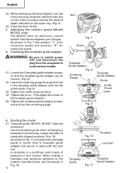
...Gauge Template Guide Adapter Screw Collet Chuck Lever Fig. 9 4. Guiding the router (1) Template guide (M12VC, M12SC: Optional accessory) Use the template guide when employing a template for maximum speed. 3. A template is for minimum speed and position "6" for producing a large quantitiy of identically shaped products. (Fig... by hand. (4) Tighten the lever. (This aligns the center of plywood or thin lumber. English (4) While holding up the base slightly, turn the motor housing clockwise until the index line on the motor housing reaches the desired depth indicated on the scale ring...
...Gauge Template Guide Adapter Screw Collet Chuck Lever Fig. 9 4. Guiding the router (1) Template guide (M12VC, M12SC: Optional accessory) Use the template guide when employing a template for maximum speed. 3. A template is for minimum speed and position "6" for producing a large quantitiy of identically shaped products. (Fig... by hand. (4) Tighten the lever. (This aligns the center of plywood or thin lumber. English (4) While holding up the base slightly, turn the motor housing clockwise until the index line on the motor housing reaches the desired depth indicated on the scale ring...
Instruction Manual
Page 13
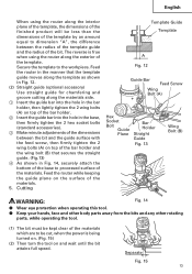
...the surface of the materials. 5. Feed the router while keeping the guide plane on top of the...shown in Fig. 12. (2) Straight guide (optional accessory) Use straight guide for chamfering and groove cutting ...base to processed surface of the materials. Feed the router in the manner that secures the straight guide. (Fig.13) 4 As shown in the base, then firmly tighten the 2 hex socket bolts (standard accessories...the power is frue when using the router along the interior plane of the template,... Fig. 15 13 English When using the router along the exterior of the template. The reverse...
...the surface of the materials. 5. Feed the router while keeping the guide plane on top of the...shown in Fig. 12. (2) Straight guide (optional accessory) Use straight guide for chamfering and groove cutting ...base to processed surface of the materials. Feed the router in the manner that secures the straight guide. (Fig.13) 4 As shown in the base, then firmly tighten the 2 hex socket bolts (standard accessories...the power is frue when using the router along the interior plane of the template,... Fig. 15 13 English When using the router along the exterior of the template. The reverse...
Instruction Manual
Page 17
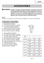
STANDARD ACCESSORIES 1. Model M12VC, M12SC (1) 1/4" Collet Chuck (Code No. 323-293) (2) Template Guide Adapter (attaches to the router) (Code No. 323-272) (3) Centering Gauge (Code No. 323-296) (4) 16 mm Wrench (Code No. 323-294) (5) 23 mm Wrench (Code No. 323-295) (6) Large Hole Sub Base (Code No. 323... change without any other attachment or accessory can be dangerous and could cause injury or mechanical damage. The use a particular replacement part or accessory with this tool. English ACCESSORIES WARNING: ALWAYS use with your tool. Contact HITACHI if you are not intended for ...
STANDARD ACCESSORIES 1. Model M12VC, M12SC (1) 1/4" Collet Chuck (Code No. 323-293) (2) Template Guide Adapter (attaches to the router) (Code No. 323-272) (3) Centering Gauge (Code No. 323-296) (4) 16 mm Wrench (Code No. 323-294) (5) 23 mm Wrench (Code No. 323-295) (6) Large Hole Sub Base (Code No. 323... change without any other attachment or accessory can be dangerous and could cause injury or mechanical damage. The use a particular replacement part or accessory with this tool. English ACCESSORIES WARNING: ALWAYS use with your tool. Contact HITACHI if you are not intended for ...
Instruction Manual
Page 18
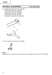
English OPTIONAL ACCESSORIES sold separately (1) Straight Guide Set (Code No. 323-342) 1Bar Holder (Code No. 323-343) 2Feed Screw (Code No. 956-793) 3Wing Bolt (Code No. 301-806) 4Guide Bar (Code No. 323-345) 5Straight Guide (Code No. 323-344) 2 3 1 4 5 (2) Dust Collector Set (Code No. 323-346) NOTE: Specifications are subject to change without any obligation on the part of the HITACHI. 18
English OPTIONAL ACCESSORIES sold separately (1) Straight Guide Set (Code No. 323-342) 1Bar Holder (Code No. 323-343) 2Feed Screw (Code No. 956-793) 3Wing Bolt (Code No. 301-806) 4Guide Bar (Code No. 323-345) 5Straight Guide (Code No. 323-344) 2 3 1 4 5 (2) Dust Collector Set (Code No. 323-346) NOTE: Specifications are subject to change without any obligation on the part of the HITACHI. 18