Specifications
Page 23
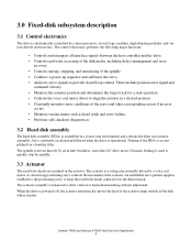
... constantly circulated and filtered when the drive is driven directly by a microprocessor, several logic modules, digital/analog modules, and various drivers and receivers. The spindle is operational. These include position error signal and estimated velocity. • Monitors the actuator position and ...determines the target track for a seek operation. • Controls the voice coil motor driver to provide closed -loop positioning servo controls the movement of the disk where it parks. An embedded servo pattern supplies feedback to...
... constantly circulated and filtered when the drive is driven directly by a microprocessor, several logic modules, digital/analog modules, and various drivers and receivers. The spindle is operational. These include position error signal and estimated velocity. • Monitors the actuator position and ...determines the target track for a seek operation. • Controls the voice coil motor driver to provide closed -loop positioning servo controls the movement of the disk where it parks. An embedded servo pattern supplies feedback to...
Specifications
Page 41
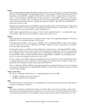
... 0 that device 1 is present. Device 0 shall allow up to 450ms for device 1 to 5 volts through a 10 kΩ resistor. shall be asserted by an Open-Drain driver and internally pulled up to avoid incorrect insertion. This line is active. to indicate that it is driven by Device 1 within 1 ms (to indicate to...
... 0 that device 1 is present. Device 0 shall allow up to 450ms for device 1 to 5 volts through a 10 kΩ resistor. shall be asserted by an Open-Drain driver and internally pulled up to avoid incorrect insertion. This line is active. to indicate that it is driven by Device 1 within 1 ms (to indicate to...
Specifications
Page 43
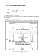
... Outputs: Input High Voltage Input Low Voltage Output High Voltage Output Low Voltage 2.0 V min 0.8 V max. 2.4 V min. 0.5 V max. 6.4.1 Signal definition (SATA model) SATA has receivers and drivers to be grounded P12 Gnd 1st mate P13 V12 12V power,pre-chage,2nd mate P14 V12 12V power P15 V12 12V power Signal Gnd...
... Outputs: Input High Voltage Input Low Voltage Output High Voltage Output Low Voltage 2.0 V min 0.8 V max. 2.4 V min. 0.5 V max. 6.4.1 Signal definition (SATA model) SATA has receivers and drivers to be grounded P12 Gnd 1st mate P13 V12 12V power,pre-chage,2nd mate P14 V12 12V power P15 V12 12V power Signal Gnd...

Specifications
Page 49
Setup time for output drivers to release - 10 Drivers to -driving until the first 70 - MODE 4 MIN MAX 0 - 20 - 20 55 0 - 0 120 25 - 57 - - 10 0 - 5 - 5 - 6.7 - MODE 5 MIN MAX 0 - 20 - 20 50 0 - - 90 17 - 38 - ...
Setup time for output drivers to release - 10 Drivers to -driving until the first 70 - MODE 4 MIN MAX 0 - 20 - 20 55 0 - 0 120 25 - 57 - - 10 0 - 5 - 5 - 6.7 - MODE 5 MIN MAX 0 - 20 - 20 50 0 - - 90 17 - 38 - ...

Specifications
Page 51
... tACK tIORDYZ PARAMETER DESCRIPTION (all values in ns) HDMARDY- to final DSTROBE time Ready to pause time Limited interlock time Maximum time allowed for output drivers to release Minimum delay time required for output Interlock time with minimum CRC word setup time at device CRC word hold time at device Hold...
... tACK tIORDYZ PARAMETER DESCRIPTION (all values in ns) HDMARDY- to final DSTROBE time Ready to pause time Limited interlock time Maximum time allowed for output drivers to release Minimum delay time required for output Interlock time with minimum CRC word setup time at device CRC word hold time at device Hold...

Specifications
Page 52
... (all values in ns) MODE 0 MIN MAX Time from DSTROBE edge to release - 10 Maximum delay time required for output 20 - Hold time for output drivers to negation of DMARQ 50 - Interlock time with minimum 20 - CRC word hold time at device 15 - Maximum time before releasing IORDY - 20 MODE 1 MIN...
... (all values in ns) MODE 0 MIN MAX Time from DSTROBE edge to release - 10 Maximum delay time required for output 20 - Hold time for output drivers to negation of DMARQ 50 - Interlock time with minimum 20 - CRC word hold time at device 15 - Maximum time before releasing IORDY - 20 MODE 1 MIN...
Specifications
Page 77
... by the Protocol, CFC-112 is also controlled. Although not specified by the member nations. In addition to the Protocol Hitachi Global Storage Technologies requires the following: • that no packaging used in this product. 7.9.3 Flammability The printed circuit boards...no manufacturing processes for parts or assemblies include printed circuit boards use controlled CFC materials. 7.9.6 Secondary circuit protection Spindle/VCM driver module includes 12 V over current protection circuit Deskstar 7K500 and Deskstar E7K500 Hard Disk Drive Specification 63 Material to build the...
... by the Protocol, CFC-112 is also controlled. Although not specified by the member nations. In addition to the Protocol Hitachi Global Storage Technologies requires the following: • that no packaging used in this product. 7.9.3 Flammability The printed circuit boards...no manufacturing processes for parts or assemblies include printed circuit boards use controlled CFC materials. 7.9.6 Secondary circuit protection Spindle/VCM driver module includes 12 V over current protection circuit Deskstar 7K500 and Deskstar E7K500 Hard Disk Drive Specification 63 Material to build the...
Specifications
Page 102
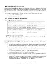
... (In LBA Mode) The following set of the protected area and to store the data in the same manner as a 6.2 GB device, any BIOS, device driver, or application software will access the drive as if it . The sequence is used to define the size of commands changes the LBA/CYL, which...
... (In LBA Mode) The following set of the protected area and to store the data in the same manner as a 6.2 GB device, any BIOS, device driver, or application software will access the drive as if it . The sequence is used to define the size of commands changes the LBA/CYL, which...


