Specifications
Page 23
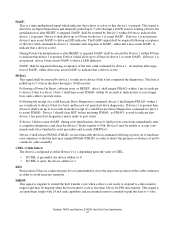
...estimated velocity. • Monitors the actuator position and determines the target track for a seek operation. • Controls the voice coil motor driver to the actuator ramp outside of the HDA is accomplished via a breather filter. The actuator is a swing-arm assembly driven by a ...microprocessor, several logic modules, digital/analog modules, and various drivers and receivers. When the drive is powered off, the actuator automatically moves the head to align the actuator in a desired position. •...
...estimated velocity. • Monitors the actuator position and determines the target track for a seek operation. • Controls the voice coil motor driver to the actuator ramp outside of the HDA is accomplished via a breather filter. The actuator is a swing-arm assembly driven by a ...microprocessor, several logic modules, digital/analog modules, and various drivers and receivers. When the drive is powered off, the actuator automatically moves the head to align the actuator in a desired position. •...
Specifications
Page 41
... 5 volts. DASP- within 400 ms to provide status. Device 1 should clear BSY before asserting PDIAG-, as either drive may be asserted by an Open-Drain driver and internally pulled up to 450 ms for PIO data transfer. CSEL (Cable Select) The drive is less than after it completes diagnostics and clear...
... 5 volts. DASP- within 400 ms to provide status. Device 1 should clear BSY before asserting PDIAG-, as either drive may be asserted by an Open-Drain driver and internally pulled up to 450 ms for PIO data transfer. CSEL (Cable Select) The drive is less than after it completes diagnostics and clear...
Specifications
Page 43
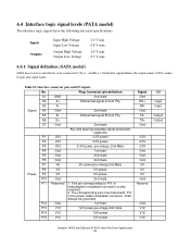
... Outputs: Input High Voltage Input Low Voltage Output High Voltage Output Low Voltage 2.0 V min 0.8 V max. 2.4 V min. 0.5 V max. 6.4.1 Signal definition (SATA model) SATA has receivers and drivers to be connected to be grounded P12 Gnd 1st mate P13 V12 12V power,pre-chage,2nd mate P14 V12 12V power P15 V12 12V...
... Outputs: Input High Voltage Input Low Voltage Output High Voltage Output Low Voltage 2.0 V min 0.8 V max. 2.4 V min. 0.5 V max. 6.4.1 Signal definition (SATA model) SATA has receivers and drivers to be connected to be grounded P12 Gnd 1st mate P13 V12 12V power,pre-chage,2nd mate P14 V12 12V power P15 V12 12V...

Specifications
Page 49
... tZIORDY tFS tCYC t2CYC tAZ tZAD tDS tDH tDZFS PARAMETER DESCRIPTION (all values in ns) MODE 0 MIN MAX Unlimited interlock time 0 - Setup time for output drivers to release - 10 Drivers to -driving until the first 70 - First DSTROBE time 0 230 Cycle time 112 -
... tZIORDY tFS tCYC t2CYC tAZ tZAD tDS tDH tDZFS PARAMETER DESCRIPTION (all values in ns) MODE 0 MIN MAX Unlimited interlock time 0 - Setup time for output drivers to release - 10 Drivers to -driving until the first 70 - First DSTROBE time 0 230 Cycle time 112 -

Specifications
Page 51
to final DSTROBE time Ready to pause time Limited interlock time Maximum time allowed for output drivers to release Minimum delay time required for output Interlock time with minimum CRC word setup time at device CRC word hold time at device Hold ...
to final DSTROBE time Ready to pause time Limited interlock time Maximum time allowed for output drivers to release Minimum delay time required for output Interlock time with minimum CRC word setup time at device CRC word hold time at device Hold ...

Specifications
Page 52
... Terminating Read DMA Table 31: Ultra DMA cycle timing chart (Device terminating Read) DMARQ DMACKSTOP HDMARDY- Limited interlock time 0 150 Maximum time allowed for output drivers to negation of DMARQ 50 - tSS tLI tLI DSTROBE DD(15:0) tAZ xxxxxx tZAH Device drives DD tMLI tACK tACK tLI tIORDYZ tCH tCS xxxxxxxxxxxxxxxxxx...
... Terminating Read DMA Table 31: Ultra DMA cycle timing chart (Device terminating Read) DMARQ DMACKSTOP HDMARDY- Limited interlock time 0 150 Maximum time allowed for output drivers to negation of DMARQ 50 - tSS tLI tLI DSTROBE DD(15:0) tAZ xxxxxx tZAH Device drives DD tMLI tACK tACK tLI tIORDYZ tCH tCS xxxxxxxxxxxxxxxxxx...
Specifications
Page 77
...Third Edition and CAN/CSA C22.2 No.950-M95 Third Edition, for use controlled CFC materials. 7.9.6 Secondary circuit protection Spindle/VCM driver module includes 12 V over current protection circuit Deskstar 7K500 and Deskstar E7K500 Hard Disk Drive Specification 63 Environmental controls meet or exceed ... in the country of the product use controlled CFCs in the manufacturing process. • that no packaging used to the Protocol Hitachi Global Storage Technologies requires the following: • that no manufacturing processes for the shipment of origin. In addition to protect the...
...Third Edition and CAN/CSA C22.2 No.950-M95 Third Edition, for use controlled CFC materials. 7.9.6 Secondary circuit protection Spindle/VCM driver module includes 12 V over current protection circuit Deskstar 7K500 and Deskstar E7K500 Hard Disk Drive Specification 63 Environmental controls meet or exceed ... in the country of the product use controlled CFCs in the manufacturing process. • that no packaging used to the Protocol Hitachi Global Storage Technologies requires the following: • that no manufacturing processes for the shipment of origin. In addition to protect the...
Specifications
Page 102
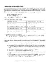
... is required to define the size of the protected area and to store the data in the same manner as a 6.2 GB device, any BIOS, device driver, or application software will access the drive as if it . Since the device functions in it were a 6.2 GB device.
... is required to define the size of the protected area and to store the data in the same manner as a 6.2 GB device, any BIOS, device driver, or application software will access the drive as if it . Since the device functions in it were a 6.2 GB device.


