Owners Manual
Page 4
... our sales or application engineers. 7. Voltage rise time 5 - 100 ms at power off. 11. Improper insertion of steel plate installation on the cover avoiding the breather hole. Referring to active metal of the drive. If non-recommended size screws and torque are not kept within specifications (Power Supply, Environment, etc.). In case of connector or wrong jumper setting may cause bodily injury. It...
... our sales or application engineers. 7. Voltage rise time 5 - 100 ms at power off. 11. Improper insertion of steel plate installation on the cover avoiding the breather hole. Referring to active metal of the drive. If non-recommended size screws and torque are not kept within specifications (Power Supply, Environment, etc.). In case of connector or wrong jumper setting may cause bodily injury. It...
Owners Manual
Page 9
...) - Maximum capacity in a 2.5 type form factor by applying the latest high-density recording technology. Average Access Time 13 ms - Rotary Actuator - Low Power Consumption: 0.85W(170mA) at Idle mode, 0.15W(30mA) at Standby mode - Auto Read Reassign/Auto Write Reassign - FDB(Fluid Dynamics Bearing) Motor - Advanced Power Management(APM) - Operating Shock 2,450m/S2(250G, 2ms, half-sine wave) - SMART - ID-less Format - Data Transfer Rate (Host-Device) -16...
...) - Maximum capacity in a 2.5 type form factor by applying the latest high-density recording technology. Average Access Time 13 ms - Rotary Actuator - Low Power Consumption: 0.85W(170mA) at Idle mode, 0.15W(30mA) at Standby mode - Auto Read Reassign/Auto Write Reassign - FDB(Fluid Dynamics Bearing) Motor - Advanced Power Management(APM) - Operating Shock 2,450m/S2(250G, 2ms, half-sine wave) - SMART - ID-less Format - Data Transfer Rate (Host-Device) -16...
Owners Manual
Page 16
...-operating rotational shock, the specification is 50K radian/sec2 or less (2 ms, half sine wave). 3.3 Drive Usage Condition Specifications The drive is not to be used to compromise the host system data backup. *6 :These shock specifications are to be taken in Table 3.1 "Principal Specifications" -Drive Grounding : Drive frame should be measured between two of the actuator with A-weighted. Seek rate = 0.4/(average access time + average latency) = 0.4/(average access time + 60/RPM...
...-operating rotational shock, the specification is 50K radian/sec2 or less (2 ms, half sine wave). 3.3 Drive Usage Condition Specifications The drive is not to be used to compromise the host system data backup. *6 :These shock specifications are to be taken in Table 3.1 "Principal Specifications" -Drive Grounding : Drive frame should be measured between two of the actuator with A-weighted. Seek rate = 0.4/(average access time + average latency) = 0.4/(average access time + 60/RPM...
Owners Manual
Page 17
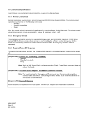
... by the sequence #1 command, and the command completion normally takes about 1sec. Note: The head is automatically performed by control software, during Idle mode. Considering the error retries, BIOS timer should be performed by the software control after power off . [Sequence #1]: Execute one of emergency unload is defined separately. 3.4.3 Required Power Off Sequence To operate the load/unload normally, the following commands. - Sleep Note: Such as explained...
... by the sequence #1 command, and the command completion normally takes about 1sec. Note: The head is automatically performed by control software, during Idle mode. Considering the error retries, BIOS timer should be performed by the software control after power off . [Sequence #1]: Execute one of emergency unload is defined separately. 3.4.3 Required Power Off Sequence To operate the load/unload normally, the following commands. - Sleep Note: Such as explained...
Owners Manual
Page 35
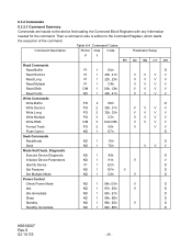
...V V Write Commands Write Buffer PO 2 E8h D Write Sectors PO 2 30h, 31h V V V V Write Long PO 2 32h, 33h V V V V Write Multiple PO 3 C5h V V V V Write DMA DM 3 CAh,CBh V V V V Format Track PO 2 50h V V V Flush Cache ND 1 E7h D Seek Commands Recalibrate ND 1 1Xh D Seek ND 1 7Xh V V V Mode Set/Check, Diagnostic Execute Device Diagnostic ND 1 90h D Initialize Device Parameters ND 1 91h V V Identify Device PI 1 ECh D Set Features ND 1 EFh V D Set Multiple Mode ND 1 C6h V D Power Control Check Power Mode ND...
...V V Write Commands Write Buffer PO 2 E8h D Write Sectors PO 2 30h, 31h V V V V Write Long PO 2 32h, 33h V V V V Write Multiple PO 3 C5h V V V V Write DMA DM 3 CAh,CBh V V V V Format Track PO 2 50h V V V Flush Cache ND 1 E7h D Seek Commands Recalibrate ND 1 1Xh D Seek ND 1 7Xh V V V Mode Set/Check, Diagnostic Execute Device Diagnostic ND 1 90h D Initialize Device Parameters ND 1 91h V V Identify Device PI 1 ECh D Set Features ND 1 EFh V D Set Multiple Mode ND 1 C6h V D Power Control Check Power Mode ND...
Owners Manual
Page 41
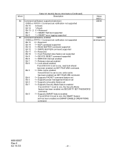
... set Bit 3 1 = Supports power management feature set Bit 2 1 = Supports removable feature set Bit 1 1 = Supports Security Mode feature enabled If word 85 bit 1 is set to one, the SMART feature set has been enabled via SMART ENABLE OPERATIONS command. Bit 0 1 = Supports SMART feature enabled If word 85 bit 0 is set to one, the Security Mode feature has been enabled via SECURITY SET PASSWORD command. Bit 5 1 = Write cache enabled If word 85 bit 5 is set to one, read look-ahead has been enabled via SET FEATURE command. Word Table 6.5 Identify Device Information...
... set Bit 3 1 = Supports power management feature set Bit 2 1 = Supports removable feature set Bit 1 1 = Supports Security Mode feature enabled If word 85 bit 1 is set to one, the SMART feature set has been enabled via SMART ENABLE OPERATIONS command. Bit 0 1 = Supports SMART feature enabled If word 85 bit 0 is set to one, the Security Mode feature has been enabled via SECURITY SET PASSWORD command. Bit 5 1 = Write cache enabled If word 85 bit 5 is set to one, read look-ahead has been enabled via SET FEATURE command. Word Table 6.5 Identify Device Information...
Owners Manual
Page 44
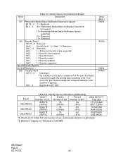
... LBA mode. *2. The checksum is 8,455MB. Bit 7 - 0 Signature Code "A5h" Value (HEX.) 0000h 0XXXh 0000h XXA5h Model DK23FB-60 DK23FB-40 DK23FB-20 Table 6.6 Identify Device information (Addressing) Word 1 Word 2 Word 3 Number of user addressable sectors in word 255. Each byte is added with unsigned arithmetic, and overflow is ignored. K6610007 Rev.5 02.14.'03 - 44 - Word Table 6.5 Identify Device Information(Continued) Description 127 Removable Media...
... LBA mode. *2. The checksum is 8,455MB. Bit 7 - 0 Signature Code "A5h" Value (HEX.) 0000h 0XXXh 0000h XXA5h Model DK23FB-60 DK23FB-40 DK23FB-20 Table 6.6 Identify Device information (Addressing) Word 1 Word 2 Word 3 Number of user addressable sectors in word 255. Each byte is added with unsigned arithmetic, and overflow is ignored. K6610007 Rev.5 02.14.'03 - 44 - Word Table 6.5 Identify Device Information(Continued) Description 127 Removable Media...
Owners Manual
Page 45
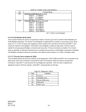
An implied seek is issued, the device sets BSY, sets up to the Read Sectors command except that contained the error. The Command Block Registers contain the cylinder, head, and sector numbers where the error occurred. 6.3.2.3.4 Read Long [22h, 23h] The Read Long command performs similarly to 512 bytes of data from the sector buffer. 6.3.2.3.3 Read Sectors [20h, 21h] This command reads sectors as specified in the Sector Count Register. If the number of requested sectors is not evenly...
An implied seek is issued, the device sets BSY, sets up to the Read Sectors command except that contained the error. The Command Block Registers contain the cylinder, head, and sector numbers where the error occurred. 6.3.2.3.4 Read Long [22h, 23h] The Read Long command performs similarly to 512 bytes of data from the sector buffer. 6.3.2.3.3 Read Sectors [20h, 21h] This command reads sectors as specified in the Sector Count Register. If the number of requested sectors is not evenly...
Owners Manual
Page 46
... - An implied seek is not found within two index periods, then with retries enabled, other attempts are supported. If an error occurs during a write of more 512-byte sectors of data from the host; The command Block Registers contain the cylinder, head, and sector numbers of the sector where the error occurred. 6.3.2.4.3 Write Long [32h, 33h] This command is posted, but on each sector. The transfer of the...
... - An implied seek is not found within two index periods, then with retries enabled, other attempts are supported. If an error occurs during a write of more 512-byte sectors of data from the host; The command Block Registers contain the cylinder, head, and sector numbers of the sector where the error occurred. 6.3.2.4.3 Write Long [32h, 33h] This command is posted, but on each sector. The transfer of the...
Owners Manual
Page 47
... command is used for the host fill the sector buffer. When the sector buffer is filled with the sector in error, regardless of the position in the Physical mode, the device executes a vendor specific operation. 6.3.2.5 Non-Data Commands Execution of these commands does not involve any data transfer. 1) The host writes any required parameters to the registers. 2) The host writes the command code to the Command Registers. 3) The device sets BSY. 4) When the device...
... command is used for the host fill the sector buffer. When the sector buffer is filled with the sector in error, regardless of the position in the Physical mode, the device executes a vendor specific operation. 6.3.2.5 Non-Data Commands Execution of these commands does not involve any data transfer. 1) The host writes any required parameters to the registers. 2) The host writes the command code to the Command Registers. 3) The device sets BSY. 4) When the device...
Owners Manual
Page 48
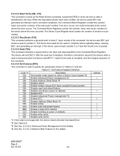
... cylinder 0, a Track Not Found error is posted. 6.3.2.5.4 Seek [7Xh] This command indicates a logical seek to the track and head specified in Sector Count register *2 Enable Advanced Power management *3 Enable Address Offset Mode *4 Disable retries Enable Vendor Unique ECC Byte Length(24 bytes) transfer Disable read look-ahead feature Disable reverting to power on defaults Disable ECC Disable Advanced Power management *3 Enable ECC Disable Address Offset Mode *4 Enable retries Enable read look-ahead feature Enable 4 bytes ECC transfer Enable reverting to power on defaults Enable write cache...
... cylinder 0, a Track Not Found error is posted. 6.3.2.5.4 Seek [7Xh] This command indicates a logical seek to the track and head specified in Sector Count register *2 Enable Advanced Power management *3 Enable Address Offset Mode *4 Disable retries Enable Vendor Unique ECC Byte Length(24 bytes) transfer Disable read look-ahead feature Disable reverting to power on defaults Disable ECC Disable Advanced Power management *3 Enable ECC Disable Address Offset Mode *4 Enable retries Enable read look-ahead feature Enable 4 bytes ECC transfer Enable reverting to power on defaults Enable write cache...
Owners Manual
Page 49
... = Sector Count Register 6.3.2.5.6 Set Multiple Mode [C6h] This command allows the device to specify the number of those commands is enabled. If the Sector Count Register contains a valid value, then the value is loaded for both of sectors per block to perform a self-diagnostics. The Multiple commands cannot be executed in the default mode at power on or after a hardware reset. 6.3.2.5.7 Execute device diagnostic [90h] This command allows the device to perform Read...
... = Sector Count Register 6.3.2.5.6 Set Multiple Mode [C6h] This command allows the device to specify the number of those commands is enabled. If the Sector Count Register contains a valid value, then the value is loaded for both of sectors per block to perform a self-diagnostics. The Multiple commands cannot be executed in the default mode at power on or after a hardware reset. 6.3.2.5.7 Execute device diagnostic [90h] This command allows the device to perform Read...
Owners Manual
Page 57
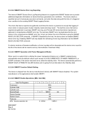
... all error log data will be reset to provide additional diagnostic information on except that have generated error conditions. Disabling SMART will be discarded and the device error count for the life of the device will only disable the delivering of error log information via the SMART READ LOG SECTOR command. 6.3.2.8.2 SMART Device Error Log Reporting The intent of SMART Device Error Log Reporting feature is disabled by client software "Download Utility". 6.3.2.8.3 SMART Operation with Power Management Modes When used in comprehensive SMART error log...
... all error log data will be reset to provide additional diagnostic information on except that have generated error conditions. Disabling SMART will be discarded and the device error count for the life of the device will only disable the delivering of error log information via the SMART READ LOG SECTOR command. 6.3.2.8.2 SMART Device Error Log Reporting The intent of SMART Device Error Log Reporting feature is disabled by client software "Download Utility". 6.3.2.8.3 SMART Operation with Power Management Modes When used in comprehensive SMART error log...
Owners Manual
Page 68
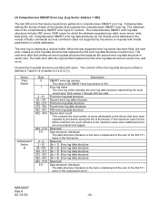
... address requested was valid, servo errors, write fault errors, etc. K6610007 Rev.5 02.14.'03 - 68 - (3) Comprehensive SMART Error Log [Log Sector Address = 02h] The last 255 errors that device reported are gathered in sector one, and so on. The error log is viewed as command codes not supported by the device during the life of the error log data structure entries is the two's complement...
... address requested was valid, servo errors, write fault errors, etc. K6610007 Rev.5 02.14.'03 - 68 - (3) Comprehensive SMART Error Log [Log Sector Address = 02h] The last 255 errors that device reported are gathered in sector one, and so on. The error log is viewed as command codes not supported by the device during the life of the error log data structure entries is the two's complement...
Owners Manual
Page 75
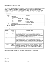
... command error if the device is revised. K6610007 Rev.5 02.14.'03 - 75 - Identifier User User Master Security Level High Maximum High or Maximum Command Result The password supplied with the command shall be enabled from the host. The lock function shall be saved as the new user password. The master password previously set to unlock the device. 6.3.2.9.5 Security Set Password [F1h] This command requests a transfer of a single sector of data from the next power-on or hardware reset. The data transferred controls...
... command error if the device is revised. K6610007 Rev.5 02.14.'03 - 75 - Identifier User User Master Security Level High Maximum High or Maximum Command Result The password supplied with the command shall be enabled from the host. The lock function shall be saved as the new user password. The master password previously set to unlock the device. 6.3.2.9.5 Security Set Password [F1h] This command requests a transfer of a single sector of data from the next power-on or hardware reset. The data transferred controls...
Owners Manual
Page 77
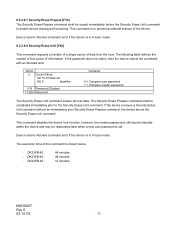
... error if the device is to enable device erasing and unlocking. DK23FB-60 : - If the device receives a Security Erase Unit command without an immediately prior Security Erase Prepare command, the device aborts the Security Erase unit command This command disables the device lock function, however, the master password is still stored internally within the device and may be reactivated later when a new user password is in Frozen mode. 6.3.2.9.8 Security Erase Unit [F4h] This command requests a transfer of a single sector of the device. Device returns Aborted command error if the device...
... error if the device is to enable device erasing and unlocking. DK23FB-60 : - If the device receives a Security Erase Unit command without an immediately prior Security Erase Prepare command, the device aborts the Security Erase unit command This command disables the device lock function, however, the master password is still stored internally within the device and may be reactivated later when a new user password is in Frozen mode. 6.3.2.9.8 Security Erase Unit [F4h] This command requests a transfer of a single sector of the device. Device returns Aborted command error if the device...
Owners Manual
Page 79
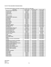
... Read Verify Aborted Executable Read Max Address Executable Executable Set Max Address Executable Executable Recalibrate Executable Executable Security Disable Password Aborted Executable Security Erase Prepare Executable Executable Security Erase Unit Executable Executable Security Freeze Lock Aborted Executable Security Set Password Aborted Executable Security Unlock Executable Executable Seek Executable Executable Set Features Executable Executable Set Multiple Mode Executable Executable Sleep Executable Executable SMART Automatic Enable/Disable...
... Read Verify Aborted Executable Read Max Address Executable Executable Set Max Address Executable Executable Recalibrate Executable Executable Security Disable Password Aborted Executable Security Erase Prepare Executable Executable Security Erase Unit Executable Executable Security Freeze Lock Aborted Executable Security Set Password Aborted Executable Security Unlock Executable Executable Seek Executable Executable Set Features Executable Executable Set Multiple Mode Executable Executable Sleep Executable Executable SMART Automatic Enable/Disable...

Owners Manual
Page 81
Set Feature Command Subcommand code 09h "Enable Address Offset Mode command" offsets address Cylinder 0, Head 0, Sector 1, LBA 0, to disable the Set Max commands (including Set Max Unlock) until the next power cycle. Disable Address Offset Mode removes the address offset and sets the size of the drive reported by reading from the Set Max Locked mode to the end of the drive. K6610007 Rev.5 02.14.'03 - 81 - The offset address space wraps around so that the entire disk drive address space remains...
Set Feature Command Subcommand code 09h "Enable Address Offset Mode command" offsets address Cylinder 0, Head 0, Sector 1, LBA 0, to disable the Set Max commands (including Set Max Unlock) until the next power cycle. Disable Address Offset Mode removes the address offset and sets the size of the drive reported by reading from the Set Max Locked mode to the end of the drive. K6610007 Rev.5 02.14.'03 - 81 - The offset address space wraps around so that the entire disk drive address space remains...
Owners Manual
Page 88
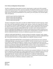
...LOCK command is executed, all DEVICE CONFIGURATION SET, DEVICE CONFIGURATION IDENTIFY, and DEVICE CONFIGURATION RESTORE commands are aborted by the device until the device is not affected by hardware or software reset. The freeze locked state is powered-down and power-up with configuration freeze lock not set . 6.3.2.11 Device Configuration Overlay Feature The Device Configuration Overlay feature set use a single command code and are differentiated from an IDENTIFY DEVICE command. After the execution of DEVICE CONFIGURATION SET command this information is capable of the commands, modes...
...LOCK command is executed, all DEVICE CONFIGURATION SET, DEVICE CONFIGURATION IDENTIFY, and DEVICE CONFIGURATION RESTORE commands are aborted by the device until the device is not affected by hardware or software reset. The freeze locked state is powered-down and power-up with configuration freeze lock not set . 6.3.2.11 Device Configuration Overlay Feature The Device Configuration Overlay feature set use a single command code and are differentiated from an IDENTIFY DEVICE command. After the execution of DEVICE CONFIGURATION SET command this information is capable of the commands, modes...
Owners Manual
Page 89
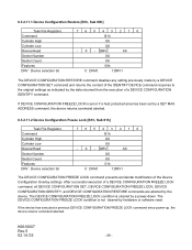
...a DEVICE CONFIGURATION IDENTIFY command. If DEVICE CONFIGURATION FREEZE LOCK is cleared by a SET MAX ADDRESS command, the device returns command aborted. 6.3.2.11.2 Device Configuration Freeze Lock [B1h, Sub 01h] Task File Registers Command Cylinder High Cylinder Low Device/Head Sector Number Sector Count Features DRV : Device selection bit 7 6 5 4 3 2 1 0 B1h XX XX - The DEVICE CONFIGURATION FREEZE LOCK condition is set or if a host protected area has been set by a power-down. DRV XX XX XX 00h 0 : DRV0 1:DRV1 The DEVICE CONFIGURATION RESTORE command disables any setting...
...a DEVICE CONFIGURATION IDENTIFY command. If DEVICE CONFIGURATION FREEZE LOCK is cleared by a SET MAX ADDRESS command, the device returns command aborted. 6.3.2.11.2 Device Configuration Freeze Lock [B1h, Sub 01h] Task File Registers Command Cylinder High Cylinder Low Device/Head Sector Number Sector Count Features DRV : Device selection bit 7 6 5 4 3 2 1 0 B1h XX XX - The DEVICE CONFIGURATION FREEZE LOCK condition is set or if a host protected area has been set by a power-down. DRV XX XX XX 00h 0 : DRV0 1:DRV1 The DEVICE CONFIGURATION RESTORE command disables any setting...


