
User Manual
Page 4
... the breather hole. Referring to the PCBA of personal injury. 2. Shock can help to circuit or component failure. Since the drive uses glass media for power supply. Warranty void in life support devices or systems or other objects. Handle with care. 4. Do not cover the breather hole. Voltage rise time 5 - 100 ms...
... the breather hole. Referring to the PCBA of personal injury. 2. Shock can help to circuit or component failure. Since the drive uses glass media for power supply. Warranty void in life support devices or systems or other objects. Handle with care. 4. Do not cover the breather hole. Voltage rise time 5 - 100 ms...
User Manual
Page 38
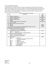
...3 Number of logical heads 4 - 5 Retired 6 Number of logical sectors per logical track 7-9 Vendor specific 10-19 Serial number (20 ASCII characters) 20 Retired 21 Retired 22 Number of ECC bytes passed on READ/WRITE LONG commands 23-26 Firmware revision(8 ASCII Characters) 27-46 Model ...number(40 ASCII Characters) DK23EB-40: "HITACHI_DK23EB-40" 47 Number of sectors on multiple commands Bit 15 - 8 80h (fixed) Bit 7 - 0 Number of sectors on multiple command 48 Double word I/O not supported 0000h = cannot perform double word I/O 0001h = can perform...
...3 Number of logical heads 4 - 5 Retired 6 Number of logical sectors per logical track 7-9 Vendor specific 10-19 Serial number (20 ASCII characters) 20 Retired 21 Retired 22 Number of ECC bytes passed on READ/WRITE LONG commands 23-26 Firmware revision(8 ASCII Characters) 27-46 Model ...number(40 ASCII Characters) DK23EB-40: "HITACHI_DK23EB-40" 47 Number of sectors on multiple commands Bit 15 - 8 80h (fixed) Bit 7 - 0 Number of sectors on multiple command 48 Double word I/O not supported 0000h = cannot perform double word I/O 0001h = can perform...

User Manual
Page 39
...-word DMA transfer Bit 15 - 8 Multi-word DMA transfer mode active Bit 7 - 0Multi-word DMA transfer mode supported 64 Flow control PIO transfer Modes supported Bit 15 - 2 0 = Reserved Bit 1 1 = PIO Mode 4 supported Bit 0 1 = PIO Mode 3 supported 65 Minimum Multi-word DMA Transfer Cycle Time Per Word(ns) 66 Manufacturer's Recommended Multi-word DMA Cycle...
...-word DMA transfer Bit 15 - 8 Multi-word DMA transfer mode active Bit 7 - 0Multi-word DMA transfer mode supported 64 Flow control PIO transfer Modes supported Bit 15 - 2 0 = Reserved Bit 1 1 = PIO Mode 4 supported Bit 0 1 = PIO Mode 3 supported 65 Minimum Multi-word DMA Transfer Cycle Time Per Word(ns) 66 Manufacturer's Recommended Multi-word DMA Cycle...

User Manual
Page 40
... 1 = Host Protected Area feature set supported Bit 9 1 = DEVICE RESET command supported Bit 8 1 = SERVICE interrupt supported Bit 7 1 = Release interrupt supported Bit 6 1 = Look-ahead supported Bit 5 1 = Write cache supported Bit 4 1 = Supports PACKET command feature set Bit 3 1 = Supports power management feature set Bit 2 1 = Supports removable feature set Bit 1 1 = Supports security feature set Bit 0 1 = Supports SMART feature set 83 Command set supported 0000h or FFFFh = Command...
... 1 = Host Protected Area feature set supported Bit 9 1 = DEVICE RESET command supported Bit 8 1 = SERVICE interrupt supported Bit 7 1 = Release interrupt supported Bit 6 1 = Look-ahead supported Bit 5 1 = Write cache supported Bit 4 1 = Supports PACKET command feature set Bit 3 1 = Supports power management feature set Bit 2 1 = Supports removable feature set Bit 1 1 = Supports security feature set Bit 0 1 = Supports SMART feature set 83 Command set supported 0000h or FFFFh = Command...
User Manual
Page 41
... bit 0 is set to one, the Security Mode feature has been enabled via SECURITY SET PASSWORD command. Bit 4 1 = Supports PACKET command feature set Bit 3 1 = Supports power management feature set Bit 2 1 = Supports removable feature set Bit 1 1 = Supports Security Mode feature enabled If word 85 bit 1 is set to one, the SMART feature set has been...
... bit 0 is set to one, the Security Mode feature has been enabled via SECURITY SET PASSWORD command. Bit 4 1 = Supports PACKET command feature set Bit 3 1 = Supports power management feature set Bit 2 1 = Supports removable feature set Bit 1 1 = Supports Security Mode feature enabled If word 85 bit 1 is set to one, the SMART feature set has been...

User Manual
Page 42
... enabled Bit 4 1 = Removable Media Status Notification feature set enabled Bit 3 1 = Advanced Power Management feature set enabled Bit 2 1 = CFA feature set supported Bit 1 1 = READ/WRITE DMA QUEUED supported Bit 0 1 = DOWNLOAD MICROCODE command supported 87 Command set/feature default 0000h or FFFFh = Command set enabled Bit 8 1 = SET MAX security extension enabled by SET MAX PASSWORD...
... enabled Bit 4 1 = Removable Media Status Notification feature set enabled Bit 3 1 = Advanced Power Management feature set enabled Bit 2 1 = CFA feature set supported Bit 1 1 = READ/WRITE DMA QUEUED supported Bit 0 1 = DOWNLOAD MICROCODE command supported 87 Command set/feature default 0000h or FFFFh = Command set enabled Bit 8 1 = SET MAX security extension enabled by SET MAX PASSWORD...
User Manual
Page 44
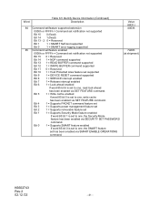
...Word Table 6.5 Identify Device Information(Continued) Description 127 Removable Media Status Notification feature set support Bit 15 - 2 0 = Reserved Bit 1 - 0 00 = Removable Media Status Notification feature set not support 01 = Removable Media Status Notification feature supported 10 = Reserved 11 = Reserved 128 Security Status Bit 15 - 9 Reserved Bit... of CYL. Bit 7 - 0 Signature Code "A5h" Value (HEX.) 0000h 0XXXh 0000h XXA5h Model DK23EB-40 Table 6.6 Identify Device information (Addressing) Word 1 Word 2 Word 3 Number of user addressable sectors in LBA mode. *2.
...Word Table 6.5 Identify Device Information(Continued) Description 127 Removable Media Status Notification feature set support Bit 15 - 2 0 = Reserved Bit 1 - 0 00 = Removable Media Status Notification feature set not support 01 = Removable Media Status Notification feature supported 10 = Reserved 11 = Reserved 128 Security Status Bit 15 - 9 Reserved Bit... of CYL. Bit 7 - 0 Signature Code "A5h" Value (HEX.) 0000h 0XXXh 0000h XXA5h Model DK23EB-40 Table 6.6 Identify Device information (Addressing) Word 1 Word 2 Word 3 Number of user addressable sectors in LBA mode. *2.

User Manual
Page 45
... bytes to determine if there has been a data error. If the number of requested sectors is similar to the Read Sectors command, except interrupts are supported. The Set Multiple Mode command, which must be executed prior to the Read Multiple command, sets the block count of each sector. When the Read...
... bytes to determine if there has been a data error. If the number of requested sectors is similar to the Read Sectors command, except interrupts are supported. The Set Multiple Mode command, which must be executed prior to the Read Multiple command, sets the block count of each sector. When the Read...

User Manual
Page 46
... 8) are repeated. 6.3.2.4.1 Write Buffer [E8h] This command allows the host to write 512 bytes of data to "ON". Only single sector Write Long operations are supported. After correctly reading a target sector, the data in the Sector Count Register, beginning at the specified sector. The Set K6602743 Rev.2 02.12.'02 - 46...
... 8) are repeated. 6.3.2.4.1 Write Buffer [E8h] This command allows the host to write 512 bytes of data to "ON". Only single sector Write Long operations are supported. After correctly reading a target sector, the data in the Sector Count Register, beginning at the specified sector. The Set K6602743 Rev.2 02.12.'02 - 46...

User Manual
Page 48
... executed, the device sets BSY=1, waits for the seek to complete, and then begins execution of the command. 6.3.2.5.5 Set Features [EFh] This command is not supported, the device returns Aborted Command Error. *2: See Table 6.8. *3: See Sec. 6.3.2.6.2 Advanced Power Management for the details. *4: See Sec. 6.3.10.2 Address Offset Feature for the seek...
... executed, the device sets BSY=1, waits for the seek to complete, and then begins execution of the command. 6.3.2.5.5 Set Features [EFh] This command is not supported, the device returns Aborted Command Error. *2: See Table 6.8. *3: See Sec. 6.3.2.6.2 Advanced Power Management for the details. *4: See Sec. 6.3.10.2 Address Offset Feature for the seek...

User Manual
Page 49
... posted and execution of the Multiple commands is loaded with the number of sectors per block to perform a self-diagnostics. When DRV0 and DRV1 are supported. If the Sector Count Register contains a valid value, then the value is loaded for all subsequent Multiple commands and execution of those commands is executed...
... posted and execution of the Multiple commands is loaded with the number of sectors per block to perform a self-diagnostics. When DRV0 and DRV1 are supported. If the Sector Count Register contains a valid value, then the value is loaded for all subsequent Multiple commands and execution of those commands is executed...

User Manual
Page 51
...any command within 200 ms after previous command completion. 6.3.2.6 Power Commands 6.3.2.6.1 Power Management Supported commands and functions: - Standby command - Standby timer (1) Low power consumption modes The drive supports the following process. - Seek and Read/Write operations are executed with seek operation, the... Immediate and Sleep commands are activated. Clear BSY bit and enable INTRQ signal - Idle command - Standby mode: State of the drive control circuit, but the spindle motor is stopped. Wait write command completion - Stop the spindle motor - Idle mode: Refer to...
...any command within 200 ms after previous command completion. 6.3.2.6 Power Commands 6.3.2.6.1 Power Management Supported commands and functions: - Standby command - Standby timer (1) Low power consumption modes The drive supports the following process. - Seek and Read/Write operations are executed with seek operation, the... Immediate and Sleep commands are activated. Clear BSY bit and enable INTRQ signal - Idle command - Standby mode: State of the drive control circuit, but the spindle motor is stopped. Wait write command completion - Stop the spindle motor - Idle mode: Refer to...

User Manual
Page 52
... 86 Bit 3: IF this bit is set to the performance level and the power consumption level. The device automatically moves to FEh, the performance is supported. - (3) Standby Timer Standby timer is changeable using Idle and Standby commands. The device performs an intelligent power saving control based on the selected pattern by...
... 86 Bit 3: IF this bit is set to the performance level and the power consumption level. The device automatically moves to FEh, the performance is supported. - (3) Standby Timer Standby timer is changeable using Idle and Standby commands. The device performs an intelligent power saving control based on the selected pattern by...

User Manual
Page 53
... modes called Active Idle mode and Low Power Idle mode. K6602743 Rev.2 02.12.'02 - 53 - (2) Active Idle Mode/Low Power Idle Mode The device supports two kind of APM function is lower power mode than Active Idle mode. (3) Low Power Consumption Mode Transition Table 6.10 Low Power Consumption Mode Transition...
... modes called Active Idle mode and Low Power Idle mode. K6602743 Rev.2 02.12.'02 - 53 - (2) Active Idle Mode/Low Power Idle Mode The device supports two kind of APM function is lower power mode than Active Idle mode. (3) Low Power Consumption Mode Transition Table 6.10 Low Power Consumption Mode Transition...

User Manual
Page 56
Support of this feature set is indicated in analyzing the status of the device. If one or more attribute values are used for that may be ... degrading or fault condition. The device manufacturer through design and reliability testing and analysis determine the numerical values of a degrading or fault condition. The commands supported by the device are the specific performance or calibration parameters that is used in bit 0 of word 82 of the Identify Device response. Accordingly, lower...
Support of this feature set is indicated in analyzing the status of the device. If one or more attribute values are used for that may be ... degrading or fault condition. The device manufacturer through design and reliability testing and analysis determine the numerical values of a degrading or fault condition. The commands supported by the device are the specific performance or calibration parameters that is used in bit 0 of word 82 of the Identify Device response. Accordingly, lower...

User Manual
Page 71
...Set Password − Security Unlock − Security Erase Prepare − Security Erase Unit − Security Freeze Lock − Security Disable Password Support of the security mode feature set is indicated in a addition to the User password. When the security level is set to user data stored ...Setting the Master password does not enable the password system. When the security level is set to the internal disk device. The commands supported by sending a user password to unlock the device. Security Mode Feature The Security Mode feature set a new master password using the ...
...Set Password − Security Unlock − Security Erase Prepare − Security Erase Unit − Security Freeze Lock − Security Disable Password Support of the security mode feature set is indicated in a addition to the User password. When the security level is set to user data stored ...Setting the Master password does not enable the password system. When the security level is set to the internal disk device. The commands supported by sending a user password to unlock the device. Security Mode Feature The Security Mode feature set a new master password using the ...

User Manual
Page 77
... to frozen mode. K6602743 Rev.2 02.12.'02 - 77 - Then the device checks the transferred password. Device returns Aborted command error if command is not supported, the device is in Locked mode, or the device is in frozen mode, the command executes and the device remains in Locked Mode. If Security...
... to frozen mode. K6602743 Rev.2 02.12.'02 - 77 - Then the device checks the transferred password. Device returns Aborted command error if command is not supported, the device is in Locked mode, or the device is in frozen mode, the command executes and the device remains in Locked Mode. If Security...

User Manual
Page 80
...the data in the user area when operating in a reserved are on disk drive, Address Offset Feature provides a Set Feature function to the Set Max Unlocked mode. Identify Device Word 83 bit 7.indicates the device supports the Set Features Address Offset Mode. The Set Max Unlock command changes the ...device from a predefined address on a disk drive. The Set Max pointer is set to the size specified in the Set Max ...
...the data in the user area when operating in a reserved are on disk drive, Address Offset Feature provides a Set Feature function to the Set Max Unlocked mode. Identify Device Word 83 bit 7.indicates the device supports the Set Features Address Offset Mode. The Set Max Unlock command changes the ...device from a predefined address on a disk drive. The Set Max pointer is set to the size specified in the Set Max ...
User Manual
Page 87
..., modes, capacity, and feature sets that the device is capable of the commands, modes, and features sets that a device reports as supported in the IDENTIFY DEVICE command response as well as the capacity reported. If a DEVICE CONFIGURATION FREEZE LOCK command has been issued since the ...device powered-up again. Since a host protected area may be lost if the capacity of DEVICE CONFIGURATION SET command this information is supported and enabled can be lost if the capacity of the Device Configuration Overlay feature set affects the IDENTIFY DEVICE command responses. A device ...
..., modes, capacity, and feature sets that the device is capable of the commands, modes, and features sets that a device reports as supported in the IDENTIFY DEVICE command response as well as the capacity reported. If a DEVICE CONFIGURATION FREEZE LOCK command has been issued since the ...device powered-up again. Since a host protected area may be lost if the capacity of DEVICE CONFIGURATION SET command this information is supported and enabled can be lost if the capacity of the Device Configuration Overlay feature set affects the IDENTIFY DEVICE command responses. A device ...

User Manual
Page 89
... - 6 0 = Reserved bit 5 1 = Ultra DMA mode 5 and below are supported bit 4 1 = Ultra DMA mode 4 and below are supported bit 3 1 = Ultra DMA mode 3 and below are supported bit 2 1 = Ultra DMA mode 2 and below are supported bit 1 1 = Ultra DMA mode 1 and below are supported bit 0 1 = Ultra DMA mode 0 is supported Value (HEX.) 0001h 0007h 003Fh K6602743 Rev.2 02.12...
... - 6 0 = Reserved bit 5 1 = Ultra DMA mode 5 and below are supported bit 4 1 = Ultra DMA mode 4 and below are supported bit 3 1 = Ultra DMA mode 3 and below are supported bit 2 1 = Ultra DMA mode 2 and below are supported bit 1 1 = Ultra DMA mode 1 and below are supported bit 0 1 = Ultra DMA mode 0 is supported Value (HEX.) 0001h 0007h 003Fh K6602743 Rev.2 02.12...