
User Manual
Page 5
... any damage. (Keep some extra packages for the drive transportation) 21. Hitachi makes no representations or warranties with pallet to protect from time to time in a box. 20. Hitachi does not perform data recovery. 23. Further Hitachi reserves the right to revise this publication and to make...implied warranties or merchantability or fitness for accidents, back up data. Safety Instructions (Continued) Caution 19. Prevent humidity when the drive is correct please feel free to ensure that the information provided herein is packed in the content hereof without obligation to the ...
... any damage. (Keep some extra packages for the drive transportation) 21. Hitachi makes no representations or warranties with pallet to protect from time to time in a box. 20. Hitachi does not perform data recovery. 23. Further Hitachi reserves the right to revise this publication and to make...implied warranties or merchantability or fitness for accidents, back up data. Safety Instructions (Continued) Caution 19. Prevent humidity when the drive is correct please feel free to ensure that the information provided herein is packed in the content hereof without obligation to the ...

User Manual
Page 6
... Off Sequence 4.0 Installation 4.1 Installation Direction 4.2 Mounting HDD 4.2.1 Mounting HDD with Screws 4.2.2 Single HDD Test Condition 4.2.3 Attention for HDD Installation 4.3 Drive Address Setting(DRIVE 0/DRIVE 1) 4.4 Dimensions 5.0 Packing and Handling 5.1 Packing 5.2 Handling 6.0 Interface 6.1 Power Interface 6.2 Physical Interface 6.2.1 Connector 6.2.2 Connector Pin Assignment 6.2.3...2 9 9 10 12 13 13 15 16 17 17 17 17 18 18 19 19 20 21 21 22 23 23 24 25 25 26 26 27 28 31 31 31 31 32...
... Off Sequence 4.0 Installation 4.1 Installation Direction 4.2 Mounting HDD 4.2.1 Mounting HDD with Screws 4.2.2 Single HDD Test Condition 4.2.3 Attention for HDD Installation 4.3 Drive Address Setting(DRIVE 0/DRIVE 1) 4.4 Dimensions 5.0 Packing and Handling 5.1 Packing 5.2 Handling 6.0 Interface 6.1 Power Interface 6.2 Physical Interface 6.2.1 Connector 6.2.2 Connector Pin Assignment 6.2.3...2 9 9 10 12 13 13 15 16 17 17 17 17 18 18 19 19 20 21 21 22 23 23 24 25 25 26 26 27 28 31 31 31 31 32...
User Manual
Page 14
... failure. the average latency and one revolution). *9 :Measured while reading or writing 16 sectors of data located on the same track before this drive and in the nominal condition in case of spin up retry operation. K6602743 Rev.2 02.12.'02 - 14 - This maximum time is recommended... at the connector of the PCBA of this power transition. *8 :Measured during start up to 20 seconds in which the power voltage and the temperature are unloaded. *7 :Power mode automatically enters to Section 6.1. *6 :This value is calculated under the...
... failure. the average latency and one revolution). *9 :Measured while reading or writing 16 sectors of data located on the same track before this drive and in the nominal condition in case of spin up retry operation. K6602743 Rev.2 02.12.'02 - 14 - This maximum time is recommended... at the connector of the PCBA of this power transition. *8 :Measured during start up to 20 seconds in which the power voltage and the temperature are unloaded. *7 :Power mode automatically enters to Section 6.1. *6 :This value is calculated under the...
User Manual
Page 15
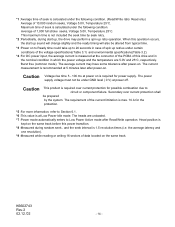
... - Please see specification 5.1 Packing for reference. *3 :In case of the drive. Item Specification DK23EB-40 1 Ambient *1 Operational 5 to 55°C temperature Non-operational -40 to 70°C *2 Temperature gradient Max. 20°C /hour 2 Relative humidity Operational 5 to 90 % Non-operational 5 to 0°C, the drive should be packed in the table below. Ambient temperature 55...
... - Please see specification 5.1 Packing for reference. *3 :In case of the drive. Item Specification DK23EB-40 1 Ambient *1 Operational 5 to 55°C temperature Non-operational -40 to 70°C *2 Temperature gradient Max. 20°C /hour 2 Relative humidity Operational 5 to 90 % Non-operational 5 to 0°C, the drive should be packed in the table below. Ambient temperature 55...

User Manual
Page 16
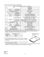
... sales representatives or application engineers if the drive may be operated outside these conditions. -Power...side mounting holes) should be grounded to the drive. Grounding noise should be measured through 50 ...half sine wave). 3.3 Drive Usage Condition Specifications The drive is not to be used...(measuring between electrical ground and system frame ground without the drive. The heads are the maximum sound power levels with A-... Measurements are defined for the drive can be calculated as shown ...Drive Grounding : Drive frame should be less than 50 mAp-p (Frequency Range: less than...
... sales representatives or application engineers if the drive may be operated outside these conditions. -Power...side mounting holes) should be grounded to the drive. Grounding noise should be measured through 50 ...half sine wave). 3.3 Drive Usage Condition Specifications The drive is not to be used...(measuring between electrical ground and system frame ground without the drive. The heads are the maximum sound power levels with A-... Measurements are defined for the drive can be calculated as shown ...Drive Grounding : Drive frame should be less than 50 mAp-p (Frequency Range: less than...

User Manual
Page 17
Since normal unload can not be set to maximum 20,000 times during HDD life. Standby Immediate - Note: The head is unload by the sequence #1 command, and the command completion normally takes about 400 ms. ... Unload The emergency unload is occurred by unexpected power down, and is limited to over 30 sec by the Host side. [Sequence #3]: Power off the drive Above sequence is required for the Host system at Power off, Suspend and Hibernation operations. 3.4 Load/Unload Specifications Load /Unload is a mechanism to load/unload...
Since normal unload can not be set to maximum 20,000 times during HDD life. Standby Immediate - Note: The head is unload by the sequence #1 command, and the command completion normally takes about 400 ms. ... Unload The emergency unload is occurred by unexpected power down, and is limited to over 30 sec by the Host side. [Sequence #3]: Power off the drive Above sequence is required for the Host system at Power off, Suspend and Hibernation operations. 3.4 Load/Unload Specifications Load /Unload is a mechanism to load/unload...

User Manual
Page 20
... fixed by tension of I =7.3X10⁻⁴ kg m2 ) HDD X Axis Direction K6602743 Rev.2 02.12.'02 ABS-sheet (t = 5mm) Figure 4-3 Single HDD Test Condition - 20 - The body weight is placed on the HDD as shown in Figure 4-3. Material : SS41 with ELP-coat Weight : M=0.66kg (92) Inertia : I=7.3X10 kg m Y ... To optimize the performance, keep the following instructions. 1) For the Single HDD test, HDD should be placed on a soft sponge sheet or hard surface at seek operations or spindle motor rotation. If the HDD is provided for preventing the HDD movement or HDD floating by external force min...
... fixed by tension of I =7.3X10⁻⁴ kg m2 ) HDD X Axis Direction K6602743 Rev.2 02.12.'02 ABS-sheet (t = 5mm) Figure 4-3 Single HDD Test Condition - 20 - The body weight is placed on the HDD as shown in Figure 4-3. Material : SS41 with ELP-coat Weight : M=0.66kg (92) Inertia : I=7.3X10 kg m Y ... To optimize the performance, keep the following instructions. 1) For the Single HDD test, HDD should be placed on a soft sponge sheet or hard surface at seek operations or spindle motor rotation. If the HDD is provided for preventing the HDD movement or HDD floating by external force min...

User Manual
Page 27
...- 39 5VDC(Logic) 41 GND(Logic) 43 B JUMPER0 D JUMPER2 F KEY(Removed) 2 GND 4 DD8 6 DD9 8 DD10 10 DD11 12 DD12 14 DD13 16 DD14 18 DD15 20 KEY(Removed) 22 GND 24 GND 26 GND 28 CSEL 30 GND 32 IOCS16- 34 PDIAG- 36 DA2 38 CS1- 40 GND(Motor) 42 5VDC...
...- 39 5VDC(Logic) 41 GND(Logic) 43 B JUMPER0 D JUMPER2 F KEY(Removed) 2 GND 4 DD8 6 DD9 8 DD10 10 DD11 12 DD12 14 DD13 16 DD14 18 DD15 20 KEY(Removed) 22 GND 24 GND 26 GND 28 CSEL 30 GND 32 IOCS16- 34 PDIAG- 36 DA2 38 CS1- 40 GND(Motor) 42 5VDC...

User Manual
Page 30
...21 29 PIN-A,B,D I/O type I/O O I /F cable should be no longer than 50cm(20 inches) including the circuit pattern length in response to DMARQ to either acknowledge that data has been accepted, or that Drive 1 is present when the power is ready to +5.25V or an open circuit Low level... host in the host system. At command completion, the device de-asserts this signal, used for the detail. See Sec. 4.3 " Drive Address Setting (Drive 0/Drive 1)" for DMA data transfers between host and device, when it may cause factional degradations or some errors. The device shall assert this signal...
...21 29 PIN-A,B,D I/O type I/O O I /F cable should be no longer than 50cm(20 inches) including the circuit pattern length in response to DMARQ to either acknowledge that data has been accepted, or that Drive 1 is present when the power is ready to +5.25V or an open circuit Low level... host in the host system. At command completion, the device de-asserts this signal, used for the detail. See Sec. 4.3 " Drive Address Setting (Drive 0/Drive 1)" for DMA data transfers between host and device, when it may cause factional degradations or some errors. The device shall assert this signal...
User Manual
Page 38
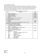
... 3 Number of logical heads 4 - 5 Retired 6 Number of logical sectors per logical track 7-9 Vendor specific 10-19 Serial number (20 ASCII characters) 20 Retired 21 Retired 22 Number of ECC bytes passed on READ/WRITE LONG commands 23-26 Firmware revision(8 ASCII Characters) 27-46 Model number...(40 ASCII Characters) DK23EB-40: "HITACHI_DK23EB-40" 47 Number of sectors on multiple commands Bit 15 - 8 80h (fixed) Bit 7 - ...
... 3 Number of logical heads 4 - 5 Retired 6 Number of logical sectors per logical track 7-9 Vendor specific 10-19 Serial number (20 ASCII characters) 20 Retired 21 Retired 22 Number of ECC bytes passed on READ/WRITE LONG commands 23-26 Firmware revision(8 ASCII Characters) 27-46 Model number...(40 ASCII Characters) DK23EB-40: "HITACHI_DK23EB-40" 47 Number of sectors on multiple commands Bit 15 - 8 80h (fixed) Bit 7 - ...

User Manual
Page 54
6.3.2.6.4 Idle [97h, E3h] This command causes the device to enter to the Idle Mode. Sector Count Value SC = 0 0 By the power on default, the Standby timer is disabled. The Sector Count Register sets the standby timer value.
6.3.2.6.4 Idle [97h, E3h] This command causes the device to enter to the Idle Mode. Sector Count Value SC = 0 0 By the power on default, the Standby timer is disabled. The Sector Count Register sets the standby timer value.

User Manual
Page 96
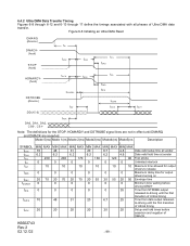
... Valid *2 Read Data Valid *2 t7 IOCS16- Setup 25 t2 DIOR-/DIOW- Data Hold 10 t5 DIOR- Data tristate t7 Addr Valid To IOCS16- Data Setup 20 t6 DIOR- Negation (MAX) t9 DIOR-/DIOW- 6.4 Interface Signal Timing 6.4.1 Data Transfer Timing Figures 6-4, 6-5, and 6-7 show the timing for asserting interface signals...10 MAX(ns) 30 40 30 K6602743 Rev.2 02.12.'02 - 96 - Pulse Width 70 t2i DIOR-/DIOW- Data Hold 5 t6Z DIOR- Data Setup 20 t4 DIOW- Assertion(MAX) t8 Addr Valid To IOCS16- to DIOR-/DIOW- Figure 6-4 PIO Data Transfer Timing(Mode 4) t0 Addr Valid *1 t1 t2 ...
... Valid *2 Read Data Valid *2 t7 IOCS16- Setup 25 t2 DIOR-/DIOW- Data Hold 10 t5 DIOR- Data tristate t7 Addr Valid To IOCS16- Data Setup 20 t6 DIOR- Negation (MAX) t9 DIOR-/DIOW- 6.4 Interface Signal Timing 6.4.1 Data Transfer Timing Figures 6-4, 6-5, and 6-7 show the timing for asserting interface signals...10 MAX(ns) 30 40 30 K6602743 Rev.2 02.12.'02 - 96 - Pulse Width 70 t2i DIOR-/DIOW- Data Hold 5 t6Z DIOR- Data Setup 20 t4 DIOW- Assertion(MAX) t8 Addr Valid To IOCS16- to DIOR-/DIOW- Figure 6-4 PIO Data Transfer Timing(Mode 4) t0 Addr Valid *1 t1 t2 ...

User Manual
Page 98
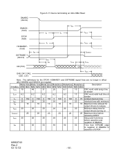
Data Setup 20 tGw DIOW- Setup 0 tJ DIOR- / DIOW- Data Setup 20 tH DIOW- Data Hold 10 tI DMACK to DIOR-/DIOW- 25 tN CS(1:0) hold 25 tZ DMACK- tGr DIOR- Negated Pulse Width 25 tL DIOR- / DIOW- to DMARQ Delay 35 tM CS(1:0) valid to DIOR- / DIOW- to DMACK Hold 5 tK DIOR- / DIOW- to tristate 25 K6602743 Rev.2 02.12.'02 - 98 -
Data Setup 20 tGw DIOW- Setup 0 tJ DIOR- / DIOW- Data Setup 20 tH DIOW- Data Hold 10 tI DMACK to DIOR-/DIOW- 25 tN CS(1:0) hold 25 tZ DMACK- tGr DIOR- Negated Pulse Width 25 tL DIOR- / DIOW- to DMARQ Delay 35 tM CS(1:0) valid to DIOR- / DIOW- to DMACK Hold 5 tK DIOR- / DIOW- to tristate 25 K6602743 Rev.2 02.12.'02 - 98 -
User Manual
Page 99
... DMARQ and DMACK are asserted. Note: The definitions for output drivers turning on tENV tZIORDY 20 70 20 70 20 70 20 55 20 55 20 50 Envelope time 0 0 0 0 0 0 Minimum time waiting before driving IORDY tZFS 0 0 0 0 0 35 Time from data output released- Mode 0(ns) Mode 1(ns) Mode 2(ns) Mode3(ns) Mode4(ns) Mode5(ns Description ) SYMBOL MIN...
... DMARQ and DMACK are asserted. Note: The definitions for output drivers turning on tENV tZIORDY 20 70 20 70 20 70 20 55 20 55 20 50 Envelope time 0 0 0 0 0 0 Minimum time waiting before driving IORDY tZFS 0 0 0 0 0 35 Time from data output released- Mode 0(ns) Mode 1(ns) Mode 2(ns) Mode3(ns) Mode4(ns) Mode5(ns Description ) SYMBOL MIN...

User Manual
Page 100
...) MIN MAX MIN MAX MIN MAX MIN MAX MIN MAX 112 73 54 39 25 230 153 115 86 57 15 10 7 7 5 5 5 5 5 5 70 48 31 20 6.7 6.2 6.2 6.2 6.2 6.2 14.7 9.7 6.8 6.8 4.8 4.8 4.8 4.8 4.8 4.8 72.9 50.9 33.9 22.6 9.5 9.0 9.0 9.0 9.0 9.0 Mode5(ns) MIN MAX 16.8 38 4 4.6 4.8 4.8 2.3 2.8 6.0 6.0 Description Cycle time allowing for asymmetry and clock variation Two cycle time allowing for...
...) MIN MAX MIN MAX MIN MAX MIN MAX MIN MAX 112 73 54 39 25 230 153 115 86 57 15 10 7 7 5 5 5 5 5 5 70 48 31 20 6.7 6.2 6.2 6.2 6.2 6.2 14.7 9.7 6.8 6.8 4.8 4.8 4.8 4.8 4.8 4.8 72.9 50.9 33.9 22.6 9.5 9.0 9.0 9.0 9.0 9.0 Mode5(ns) MIN MAX 16.8 38 4 4.6 4.8 4.8 2.3 2.8 6.0 6.0 Description Cycle time allowing for asymmetry and clock variation Two cycle time allowing for...
User Manual
Page 102
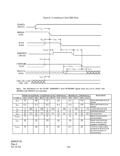
Note: The definitions for output drivers turning on tIORDYZ 20 20 20 20 20 20 Maximum time before releasing IORDY tACK 20 20 20 20 20 20 Setup and hold times before assertion and negation of DMACK_ tSS 50 50 50 50 50 50 Time from STROBE edge to...sender tLI 0 150 0 150 0 150 0 100 0 100 0 75 Limited interlock time tMLI 20 20 20 20 20 20 Interlock time with minimum tAZ 10 10 10 10 10 10 Maximum time allowed for output drivers to release tZAH 20 20 20 20 20 20 Minimum delay time for the STOP, HDMARDY and DSTROBE signal lines are no longer in...
Note: The definitions for output drivers turning on tIORDYZ 20 20 20 20 20 20 Maximum time before releasing IORDY tACK 20 20 20 20 20 20 Setup and hold times before assertion and negation of DMACK_ tSS 50 50 50 50 50 50 Time from STROBE edge to...sender tLI 0 150 0 150 0 150 0 100 0 100 0 75 Limited interlock time tMLI 20 20 20 20 20 20 Interlock time with minimum tAZ 10 10 10 10 10 10 Maximum time allowed for output drivers to release tZAH 20 20 20 20 20 20 Minimum delay time for the STOP, HDMARDY and DSTROBE signal lines are no longer in...

User Manual
Page 103
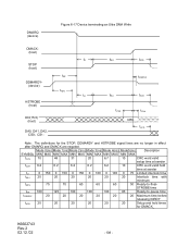
... Mode4(ns) Mode5(ns Description ) SYMBOL MIN MAX MIN MAX MIN MAX MIN MAX MIN MAX MIN MAX tCVS 70 48 31 20 6.7 10 CRC word valid setup time at sender tCVH 6.2 6.2 6.2 6.2 6.2 10 CRC word valid hold times before assertion and...20 20 20 20 20 20 Maximum time before releasing IORDY tACK 20 20 20 20 20 20 Setup and hold time at sender tLI 0 150 0 150 0 150 0 100 0 100 0 75 Limited interlock time tMLI 20 20 20 20 20 20 Interlock time with minimum tAZ 10 10 10 10 10 10 Maximum time allowed for output drivers to release tZAH 20 20 20 20 20 20...
... Mode4(ns) Mode5(ns Description ) SYMBOL MIN MAX MIN MAX MIN MAX MIN MAX MIN MAX MIN MAX tCVS 70 48 31 20 6.7 10 CRC word valid setup time at sender tCVH 6.2 6.2 6.2 6.2 6.2 10 CRC word valid hold times before assertion and...20 20 20 20 20 20 Maximum time before releasing IORDY tACK 20 20 20 20 20 20 Setup and hold time at sender tLI 0 150 0 150 0 150 0 100 0 100 0 75 Limited interlock time tMLI 20 20 20 20 20 20 Interlock time with minimum tAZ 10 10 10 10 10 10 Maximum time allowed for output drivers to release tZAH 20 20 20 20 20 20...
User Manual
Page 104
...20 70 20 70 0 0 0 tACK 20 20 20 tDZFS 70 48 31 Mode3(ns) MIN MAX 20 6.2 0 100 0 20 55 0 20 20 Mode4(ns) MIN MAX 6.7 6.2 0 100 0 20 55 0 20 6.7 Mode5(ns) Description MIN MAX 4.8 Data valid setup time at sender 4.8 Data valid hold time at sender 0 75 Limited interlock time 0 Unlimited interlock 20 50 Envelope time 0 Minimum time before driving IORDY 20... Setup and hold times before assertion and negation of DMACK_ 25 Time from data output released-to-driving until DMARQ and ...
...20 70 20 70 0 0 0 tACK 20 20 20 tDZFS 70 48 31 Mode3(ns) MIN MAX 20 6.2 0 100 0 20 55 0 20 20 Mode4(ns) MIN MAX 6.7 6.2 0 100 0 20 55 0 20 6.7 Mode5(ns) Description MIN MAX 4.8 Data valid setup time at sender 4.8 Data valid hold time at sender 0 75 Limited interlock time 0 Unlimited interlock 20 50 Envelope time 0 Minimum time before driving IORDY 20... Setup and hold times before assertion and negation of DMACK_ 25 Time from data output released-to-driving until DMARQ and ...

User Manual
Page 107
...Note: The definitions for DMACK_ tSS 50 50 50 50 50 50 Time from STROBE edge to release tIORDYZ 20 20 20 20 20 20 Maximum time before releasing IORDY tACK 20 20 20 20 20 20 Setup and hold times for the STOP, DDMARDY and HSTROBE signal lines are no longer in effect after ... 6.2 6.2 6.2 6.2 10 CRC word valid hold time at sender tLI 0 150 0 150 0 150 0 100 0 100 0 75 Limited interlock time tMLI 20 20 20 20 20 20 Interlock time with minimum tAZ 10 10 10 10 10 10 Maximum time allowed for output drivers to negation of DMARQ or assertion of STOP...
...Note: The definitions for DMACK_ tSS 50 50 50 50 50 50 Time from STROBE edge to release tIORDYZ 20 20 20 20 20 20 Maximum time before releasing IORDY tACK 20 20 20 20 20 20 Setup and hold times for the STOP, DDMARDY and HSTROBE signal lines are no longer in effect after ... 6.2 6.2 6.2 6.2 10 CRC word valid hold time at sender tLI 0 150 0 150 0 150 0 100 0 100 0 75 Limited interlock time tMLI 20 20 20 20 20 20 Interlock time with minimum tAZ 10 10 10 10 10 10 Maximum time allowed for output drivers to negation of DMARQ or assertion of STOP...
User Manual
Page 108
... time at sender tLI 0 150 0 150 0 150 0 100 0 100 0 75 Limited interlock time tMLI 20 20 20 20 20 20 Interlock time with minimum tRFS 75 70 60 60 60 50 Ready-to -pause time tIORDYZ 20 20 20 20 20 20 Maximum time before releasing IORDY tACK 20 20 20 20 20 20 Setup and hold times for the STOP, DDMARDY and HSTROBE signal lines are no...
... time at sender tLI 0 150 0 150 0 150 0 100 0 100 0 75 Limited interlock time tMLI 20 20 20 20 20 20 Interlock time with minimum tRFS 75 70 60 60 60 50 Ready-to -pause time tIORDYZ 20 20 20 20 20 20 Maximum time before releasing IORDY tACK 20 20 20 20 20 20 Setup and hold times for the STOP, DDMARDY and HSTROBE signal lines are no...
