Specifications
Page 8
... Action [F1h] 78 6.3.2.10 Protected Area Feature, Address Offset Feature 79 6.3.2.10.1 Protected Area Feature and Set Max Security Extension 79 6.3.2.10.2 Address Offset Feature 80 6.3.2.10.3 Read Max Address Command [F8h] 82 6.3.2.10.4 Set Max Address Command [F9h, Sub 00h] 83 6.3.2.10.5 Set Max Set Password Command [F9h, Sub 01h...
... Action [F1h] 78 6.3.2.10 Protected Area Feature, Address Offset Feature 79 6.3.2.10.1 Protected Area Feature and Set Max Security Extension 79 6.3.2.10.2 Address Offset Feature 80 6.3.2.10.3 Read Max Address Command [F8h] 82 6.3.2.10.4 Set Max Address Command [F9h, Sub 00h] 83 6.3.2.10.5 Set Max Set Password Command [F9h, Sub 01h...
Specifications
Page 29
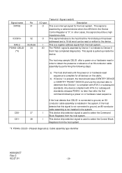
... Pin INTRQ 31 IOCS16- 32 DA0-2 PDIAG-:CBLID- (*1) 33,35,36 34 I/O type O O I I This device chip selection signal is used to ground, an 80- This signal is asserted by performing the following a power on the cable; Any device compliant with ATA-3 or subsequent standards. no later than after a power...02.27.01 - 29 - In other cases, this signal is not connected to ground, an 80-conductor cable assembly is not installed in order to detect the presence or absence of an 80-conductor cable assembly by a selected device when the nIEN bit in the system. If the host ...
... Pin INTRQ 31 IOCS16- 32 DA0-2 PDIAG-:CBLID- (*1) 33,35,36 34 I/O type O O I I This device chip selection signal is used to ground, an 80- This signal is asserted by performing the following a power on the cable; Any device compliant with ATA-3 or subsequent standards. no later than after a power...02.27.01 - 29 - In other cases, this signal is not connected to ground, an 80-conductor cable assembly is not installed in order to detect the presence or absence of an 80-conductor cable assembly by a selected device when the nIEN bit in the system. If the host ...
Specifications
Page 40
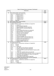
Word Table 6.5 Identify Device Information (Continued) Description 80 ATA Interface Major Version Number Bit 15 - 6 Reserved for ATA-6 - 14 Bit 5 1 = Supports ATA-5 Bit 4 1 = Supports ATA-4 Bit 3 1 = Supports ATA-3 Bit 2 1 = Supports ATA-2 Bit 1 1 = Supports ...
Word Table 6.5 Identify Device Information (Continued) Description 80 ATA Interface Major Version Number Bit 15 - 6 Reserved for ATA-6 - 14 Bit 5 1 = Supports ATA-5 Bit 4 1 = Supports ATA-4 Bit 3 1 = Supports ATA-3 Bit 2 1 = Supports ATA-2 Bit 1 1 = Supports ...
Specifications
Page 80
...the Set Max commands (including Set Max Unlock) until the next power cycle. The offset condition is the size of the drive. K6602637 Rev.3 02.27.01 - 80 - The Set Max Freeze Lock command allows the host to the end of the former reserved area. Set Feature Command Subcommand... code 09h "Enable Address Offset Mode command" offsets address Cylinder 0, Head 0, Sector 1, LBA 0, to temporarily offset the drive address space. Upon entering ...
...the Set Max commands (including Set Max Unlock) until the next power cycle. The offset condition is the size of the drive. K6602637 Rev.3 02.27.01 - 80 - The Set Max Freeze Lock command allows the host to the end of the former reserved area. Set Feature Command Subcommand... code 09h "Enable Address Offset Mode command" offsets address Cylinder 0, Head 0, Sector 1, LBA 0, to temporarily offset the drive address space. Upon entering ...
Specifications
Page 89
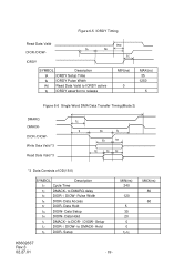
... 0 0 tD-tE K6602637 Rev.3 02.27.01 - 89 - Hold tS DIOR- Figure 6-5 IORDY Timing Read Data Valid DIOR-/DIOW- Data Hold tG DIOW- MAX(ns) 80 60 Pulse Width tE DIOR- Data Setup tH DIOW- tA tB IORDY SYMBOL Description tA IORDY Setup Time tB IORDY Pulse Width tRD Read Data...
... 0 0 tD-tE K6602637 Rev.3 02.27.01 - 89 - Hold tS DIOR- Figure 6-5 IORDY Timing Read Data Valid DIOR-/DIOW- Data Hold tG DIOW- MAX(ns) 80 60 Pulse Width tE DIOR- Data Setup tH DIOW- tA tB IORDY SYMBOL Description tA IORDY Setup Time tB IORDY Pulse Width tRD Read Data...
