Specifications
Page 4
... correct insertion. 13. Observe Clause 3.3 "Drive Usage Condition Specifications". Hot swapping (Power-on the cover avoiding the breather hole. Electro Static Discharge (ESD) can result in life support devices or systems or other objects. This product is not provided for use the size of screws and the torque recommended in case of steel plate installation on usage conditions, please consult...
... correct insertion. 13. Observe Clause 3.3 "Drive Usage Condition Specifications". Hot swapping (Power-on the cover avoiding the breather hole. Electro Static Discharge (ESD) can result in life support devices or systems or other objects. This product is not provided for use the size of screws and the torque recommended in case of steel plate installation on usage conditions, please consult...
Specifications
Page 6
... Attention for HDD Installation 4.3 Drive Address Setting(DRIVE 0/DRIVE 1) 4.4 Dimensions 5.0 Packing and Handling 5.1 Packing 5.2 Handling 6.0 Interface 6.1 Power Interface 6.2 Physical Interface 6.2.1 Connector 6.2.2 Connector Pin Assignment 6.2.3 Description of the Interface Signals 6.3 Logical Interface 6.3.1 I/O Registers 6.3.1.1 Data Register 6.3.1.2 Error Register 6.3.1.3 Features Register 6.3.1.4 Sector Count Register 6.3.1.5 Sector Number Register 6.3.1.6 Cylinder Low Register 6.3.1.7 Cylinder High Register 6.3.1.8 Device/Head Register 6.3.1.9 Status Register 6.3.1.10 Command Register...
... Attention for HDD Installation 4.3 Drive Address Setting(DRIVE 0/DRIVE 1) 4.4 Dimensions 5.0 Packing and Handling 5.1 Packing 5.2 Handling 6.0 Interface 6.1 Power Interface 6.2 Physical Interface 6.2.1 Connector 6.2.2 Connector Pin Assignment 6.2.3 Description of the Interface Signals 6.3 Logical Interface 6.3.1 I/O Registers 6.3.1.1 Data Register 6.3.1.2 Error Register 6.3.1.3 Features Register 6.3.1.4 Sector Count Register 6.3.1.5 Sector Number Register 6.3.1.6 Cylinder Low Register 6.3.1.7 Cylinder High Register 6.3.1.8 Device/Head Register 6.3.1.9 Status Register 6.3.1.10 Command Register...
Specifications
Page 8
...13 SMART Write Log Sector [B0h, Sub D6h] 70 6.3.2.9 Security Mode Feature 71 6.3.2.9.1 Security Mode Default Setting 71 6.3.2.9.2 Initial Setting of the User Password 72 6.3.2.9.3 Security Mode Operation from Power-on or Hardware Reset 72 6.3.2.9.4 User Password Lost 73 6.3.2.9.5 Security Set Password [F1h] 74 6.3.2.9.6 Security Unlock [F2h] 75 6.3.2.9.7 Security Erase Prepare [F3h] 76 6.3.2.9.8 Security Erase Unit [F4h] 76 6.3.2.9.9 Security Freeze Lock [F5h] 77 6.3.2.9.10 Security Disable Password [F6h] 77 6.3.2.9.11 Security Mode Command Action...
...13 SMART Write Log Sector [B0h, Sub D6h] 70 6.3.2.9 Security Mode Feature 71 6.3.2.9.1 Security Mode Default Setting 71 6.3.2.9.2 Initial Setting of the User Password 72 6.3.2.9.3 Security Mode Operation from Power-on or Hardware Reset 72 6.3.2.9.4 User Password Lost 73 6.3.2.9.5 Security Set Password [F1h] 74 6.3.2.9.6 Security Unlock [F2h] 75 6.3.2.9.7 Security Erase Prepare [F3h] 76 6.3.2.9.8 Security Erase Unit [F4h] 76 6.3.2.9.9 Security Freeze Lock [F5h] 77 6.3.2.9.10 Security Disable Password [F6h] 77 6.3.2.9.11 Security Mode Command Action...
Specifications
Page 9
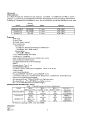
....3 02.27.01 - 9 - Embedded Sector Servo - Maximum capacity in a 2.5 type form factor by applying the latest high-density recording technology. GMR Head - Data Transfer Rate (Host-Device) -16.6 MB/sec: PIO mode-4/Multiword DMA mode-2 - 100 MB/sec: Ultra DMA mode-5 (Device-Buffer) - 16.5 to 28.7 MB/sec - Low Power Consumption: 0.65W(130mA) at Idle mode, 0.25W(50mA) at Standby mode - Operating Shock 1,764m/S2(180G, 2ms...
....3 02.27.01 - 9 - Embedded Sector Servo - Maximum capacity in a 2.5 type form factor by applying the latest high-density recording technology. GMR Head - Data Transfer Rate (Host-Device) -16.6 MB/sec: PIO mode-4/Multiword DMA mode-2 - 100 MB/sec: Ultra DMA mode-5 (Device-Buffer) - 16.5 to 28.7 MB/sec - Low Power Consumption: 0.65W(130mA) at Idle mode, 0.25W(50mA) at Standby mode - Operating Shock 1,764m/S2(180G, 2ms...
Specifications
Page 17
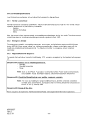
...,000 times during HDD life. The above normal unload time does not include an emergency unload as Soft Reset, Flush Cache command or Check Power Mode command does not unload the heads. Note: The head is unload by the sequence #1 command, and the command completion normally takes about 400 ms. Considering the error retries, BIOS timer should be performed by the software control after power off , Suspend and Hibernation operations...
...,000 times during HDD life. The above normal unload time does not include an emergency unload as Soft Reset, Flush Cache command or Check Power Mode command does not unload the heads. Note: The head is unload by the sequence #1 command, and the command completion normally takes about 400 ms. Considering the error retries, BIOS timer should be performed by the software control after power off , Suspend and Hibernation operations...

Specifications
Page 35
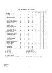
...V V Write Commands Write Buffer PO 2 E8h D Write Sectors PO 2 30h, 31h V V V V Write Long PO 2 32h, 33h V V V V Write Multiple PO 3 C5h V V V V Write DMA DM 3 CAh,CBh V V V V Format Track PO 2 50h V V V Flush Cache ND 1 E7h D Seek Commands Recalibrate ND 1 1Xh D Seek ND 1 7Xh V V V Mode Set/Check, Diagnostic Execute Device Diagnostic ND 1 90h D Initialize Device Parameters ND 1 91h V V Identify Device PI 1 ECh D Set Features ND 1 EFh V D Set Multiple Mode ND 1 C6h V D Power Control Check Power Mode ND...
...V V Write Commands Write Buffer PO 2 E8h D Write Sectors PO 2 30h, 31h V V V V Write Long PO 2 32h, 33h V V V V Write Multiple PO 3 C5h V V V V Write DMA DM 3 CAh,CBh V V V V Format Track PO 2 50h V V V Flush Cache ND 1 E7h D Seek Commands Recalibrate ND 1 1Xh D Seek ND 1 7Xh V V V Mode Set/Check, Diagnostic Execute Device Diagnostic ND 1 90h D Initialize Device Parameters ND 1 91h V V Identify Device PI 1 ECh D Set Features ND 1 EFh V D Set Multiple Mode ND 1 C6h V D Power Control Check Power Mode ND...
Specifications
Page 36
...D SMART Disable Operations ND 1 B0h D9h V D SMART Return Status ND 1 B0h DAh V D SMART Enable/Disable ND 1 B0h DBh V V D Automatic Off-line SMART Execute Off-line ND 1 B0h D4h V D Immediate SMART Read Log Sector PI 1 B0h D5h V V V D SMART Write Log Sector PO 3 B0h D6h V V V D Security Commands Security Disable Password PO 3 F6h D Security Erase Prepare ND 1 F3h D Security Erase Unit PO 3 F4h D Security Freeze Lock ND 1 F5h D Security Set Password PO 3 F1h D Security Unlock PO 3 F2h D Protected Area Commands Read Max...
...D SMART Disable Operations ND 1 B0h D9h V D SMART Return Status ND 1 B0h DAh V D SMART Enable/Disable ND 1 B0h DBh V V D Automatic Off-line SMART Execute Off-line ND 1 B0h D4h V D Immediate SMART Read Log Sector PI 1 B0h D5h V V V D SMART Write Log Sector PO 3 B0h D6h V V V D Security Commands Security Disable Password PO 3 F6h D Security Erase Prepare ND 1 F3h D Security Erase Unit PO 3 F4h D Security Freeze Lock ND 1 F5h D Security Set Password PO 3 F1h D Security Unlock PO 3 F2h D Protected Area Commands Read Max...
Specifications
Page 40
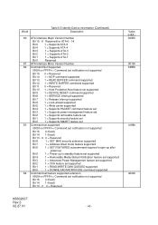
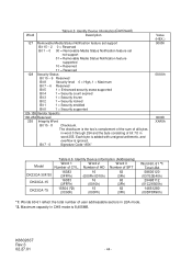
... 81 ATA Interface Minor Version Number 82 Command Set Supported 0000h or FFFFh = Command set notification not supported Bit 15 0 = Reserved Bit 14 1 = NOP command supported Bit 13 1 = READ BUFFER command supported Bit 12 1 = WRITE BUFFER command supported Bit 11 0 = Reserved Bit 10 1 = Host Protected Area feature set supported Bit 9 1 = DEVICE RESET command supported Bit 8 1 = SERVICE interrupt supported Bit 7 1 = Release interrupt supported Bit 6 1 = Look-ahead supported Bit 5 1 = Write cache supported Bit 4 1 = Supports PACKET command feature set Bit 3 1 = Supports power...
... 81 ATA Interface Minor Version Number 82 Command Set Supported 0000h or FFFFh = Command set notification not supported Bit 15 0 = Reserved Bit 14 1 = NOP command supported Bit 13 1 = READ BUFFER command supported Bit 12 1 = WRITE BUFFER command supported Bit 11 0 = Reserved Bit 10 1 = Host Protected Area feature set supported Bit 9 1 = DEVICE RESET command supported Bit 8 1 = SERVICE interrupt supported Bit 7 1 = Release interrupt supported Bit 6 1 = Look-ahead supported Bit 5 1 = Write cache supported Bit 4 1 = Supports PACKET command feature set Bit 3 1 = Supports power...
Specifications
Page 44
... 3 1 = Security frozen Bit 2 1 = Security locked Bit 1 1 = Security enabled Bit 0 1 = Security supported 129-159 Vendor Specific 160-254 Reserved 255 Integrity Word Bit 15 - 8 Checksum. Each byte is added with unsigned arithmetic, and overflow is 8,455MB. K6602637 Rev.3 02.27.01 - 44 - Bit 7 - 0 Signature Code "A5h" Value (HEX.) 0000h 0XXXh 0000h XXA5h Table 6.6 Identify Device information (Addressing) Model Word 1 Word 2 Word 3 Number of user addressable sectors...
... 3 1 = Security frozen Bit 2 1 = Security locked Bit 1 1 = Security enabled Bit 0 1 = Security supported 129-159 Vendor Specific 160-254 Reserved 255 Integrity Word Bit 15 - 8 Checksum. Each byte is added with unsigned arithmetic, and overflow is 8,455MB. K6602637 Rev.3 02.27.01 - 44 - Bit 7 - 0 Signature Code "A5h" Value (HEX.) 0000h 0XXXh 0000h XXA5h Table 6.6 Identify Device information (Addressing) Model Word 1 Word 2 Word 3 Number of user addressable sectors...

Specifications
Page 45
... errors cause the command to try and read long operations are transferred only if the error was a correctable data error. If an error occurs, the read operation, sets DRQ, clears BSY, and generates an interrupt. The Set Multiple Mode command, which the device searches for the target sector. Disk errors encountered during Read Multiple commands are made to stop after which must be transferred. 6.3.2.3.5 Read Multiple [C4h] This command is done if needed, after transfer of {Sector...
... errors cause the command to try and read long operations are transferred only if the error was a correctable data error. If an error occurs, the read operation, sets DRQ, clears BSY, and generates an interrupt. The Set Multiple Mode command, which the device searches for the target sector. Disk errors encountered during Read Multiple commands are made to stop after which must be transferred. 6.3.2.3.5 Read Multiple [C4h] This command is done if needed, after transfer of {Sector...
Specifications
Page 46
... the device. 1) The host writes any required parameters to the Features, Sector Count, Sector Number, Cylinder Low, Cylinder High, and Device/Head Registers. 2) The host writes the command code to the Command Register. 3) The device sets the DRQ when it clears BSY and set the INTRQ signal to 8) are supported. The command Block Registers contain the cylinder, head, and sector numbers of data to the Data Register. 5) The device clears DRQ and sets BSY. 6) When the device has...
... the device. 1) The host writes any required parameters to the Features, Sector Count, Sector Number, Cylinder Low, Cylinder High, and Device/Head Registers. 2) The host writes the command code to the Command Register. 3) The device sets the DRQ when it clears BSY and set the INTRQ signal to 8) are supported. The command Block Registers contain the cylinder, head, and sector numbers of data to the Data Register. 5) The device clears DRQ and sets BSY. 6) When the device has...
Specifications
Page 47
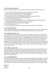
... mode, the device executes a vendor specific operation. 6.3.2.5 Non-Data Commands Execution of these commands does not involve any data transfer. 1) The host writes any required parameters to the registers. 2) The host writes the command code to the Command Registers. 3) The device sets BSY. 4) When the device has completed processing, it logically. The Partial block transfer shall be filled with the sector in the Sector Count Register. If the device is specified in error...
... mode, the device executes a vendor specific operation. 6.3.2.5 Non-Data Commands Execution of these commands does not involve any data transfer. 1) The host writes any required parameters to the registers. 2) The host writes the command code to the Command Registers. 3) The device sets BSY. 4) When the device has completed processing, it logically. The Partial block transfer shall be filled with the sector in the Sector Count Register. If the device is specified in error...
Specifications
Page 48
... 99h AAh BBh CCh 02h 82h Description Set transfer mode based on defaults Enable write cache Disable write cache Default Ö Ö *1: If the code is transferred to cylinder 0. 6.3.2.5.2 Read Verify [40h, 41h] This command is same as the Read Sectors command, except that DRQ is never set DSC=1 after the seek has Completed. Upon command completion, the Command Block Registers contain the cylinder, head, and sector numbers of the command, the device sets BSY and issues a seek to the host.
... 99h AAh BBh CCh 02h 82h Description Set transfer mode based on defaults Enable write cache Disable write cache Default Ö Ö *1: If the code is transferred to cylinder 0. 6.3.2.5.2 Read Verify [40h, 41h] This command is same as the Read Sectors command, except that DRQ is never set DSC=1 after the seek has Completed. Upon command completion, the Command Block Registers contain the cylinder, head, and sector numbers of the command, the device sets BSY and issues a seek to the host.
Specifications
Page 49
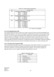
... mode, this command, it sets BSY=1 and executes the self-diagnostic operation. The Sector Count Register is disabled. Upon receipt of the devices. When DRV0 and DRV1 are supported. The Multiple commands cannot be executed in the default mode at power on or after a hardware reset. 6.3.2.5.7 Execute device diagnostic [90h] This command allows the device to perform Read Multiple and Write Multiple operations. Table 6.9 Diagnostic Codes Code Contents 01 No Error 02 Controller error 03 Sector buffer error 05 CPU error...
... mode, this command, it sets BSY=1 and executes the self-diagnostic operation. The Sector Count Register is disabled. Upon receipt of the devices. When DRV0 and DRV1 are supported. The Multiple commands cannot be executed in the default mode at power on or after a hardware reset. 6.3.2.5.7 Execute device diagnostic [90h] This command allows the device to perform Read Multiple and Write Multiple operations. Table 6.9 Diagnostic Codes Code Contents 01 No Error 02 Controller error 03 Sector buffer error 05 CPU error...
Specifications
Page 50
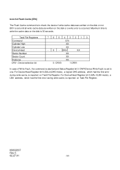
... the device if write cache data were written on Task File Register. Task File Registers Command Cylinder High Cylinder Low Device/Head Sector Number Sector Count Features DRV : Device selection bit 76543210 E7h XX XX - X - K6602637 Rev.3 02.27.01 - 50 - For Device/Head Register bit 6 LBA=0(CHS mode), a logical CHS address, which had the first error during write cache, is set until all write cache data are written on the disk is 30 seconds. For Device/Head Register bit 6 LBA=1(LBA mode), a LBA address...
... the device if write cache data were written on Task File Register. Task File Registers Command Cylinder High Cylinder Low Device/Head Sector Number Sector Count Features DRV : Device selection bit 76543210 E7h XX XX - X - K6602637 Rev.3 02.27.01 - 50 - For Device/Head Register bit 6 LBA=0(CHS mode), a logical CHS address, which had the first error during write cache, is set until all write cache data are written on the disk is 30 seconds. For Device/Head Register bit 6 LBA=1(LBA mode), a LBA address...
Specifications
Page 57
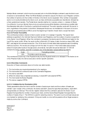
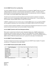
... reset to the existing SMART Read Logging Sectors. X - If a device receives a firmware modification, all times the device is disabled by client software "Download Utility". 6.3.2.8.3 SMART Operation with the time of a triggered error condition to zero by the host, the device does not disable SMART device error log. The device retains a specified amount of previously executed commands, and write this data along with Power Management Modes When used in a system that logging of errors when in reduced power modes "standby mode and sleep mode". If SMART...
... reset to the existing SMART Read Logging Sectors. X - If a device receives a firmware modification, all times the device is disabled by client software "Download Utility". 6.3.2.8.3 SMART Operation with the time of a triggered error condition to zero by the host, the device does not disable SMART device error log. The device retains a specified amount of previously executed commands, and write this data along with Power Management Modes When used in a system that logging of errors when in reduced power modes "standby mode and sleep mode". If SMART...
Specifications
Page 72
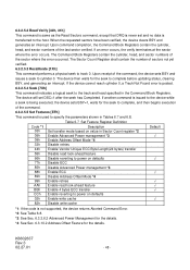
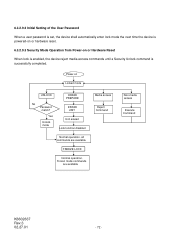
Yes Unlock mode ERASE PREPARE ERASE UNIT Unit erased Lock function disabled Normal operation, all commands are available FREEZE LOCK Normal operation, Frozen mode commands are available Media access Reject Command Non-media access Execute Command K6602637 Rev.3 02.27.01 - 72 - Power-on or Hardware Reset When lock is enabled, the device reject media access commands until a Security Unlock command is successfully completed. 6.3.2.9.2 Initial Setting of the User Password When a user password is set, the device shall automatically enter lock mode the next time the device is powered-...
Yes Unlock mode ERASE PREPARE ERASE UNIT Unit erased Lock function disabled Normal operation, all commands are available FREEZE LOCK Normal operation, Frozen mode commands are available Media access Reject Command Non-media access Execute Command K6602637 Rev.3 02.27.01 - 72 - Power-on or Hardware Reset When lock is enabled, the device reject media access commands until a Security Unlock command is successfully completed. 6.3.2.9.2 Initial Setting of the User Password When a user password is set, the device shall automatically enter lock mode the next time the device is powered-...
Specifications
Page 74
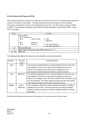
... data transferred controls the function of this sector of information. The password supplied with the command shall be used to unlock the device. The device shall then be FFFEh. K6602637 Rev.3 02.27.01 - 74 - This combination shall set is still stored in Locked mode or Frozen mode. The security level is returned in Master Password Revision Code field. The initial factory shipped value of Master Password Revision code shall be unlocked by only the user password...
... data transferred controls the function of this sector of information. The password supplied with the command shall be used to unlock the device. The device shall then be FFFEh. K6602637 Rev.3 02.27.01 - 74 - This combination shall set is still stored in Locked mode or Frozen mode. The security level is returned in Master Password Revision Code field. The initial factory shipped value of Master Password Revision code shall be unlocked by only the user password...
Specifications
Page 78
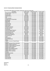
...Sectors Aborted Executable Read Verify Aborted Executable Read Max Address Executable Executable Set Max Address Executable Executable Recalibrate Executable Executable Security Disable Password Aborted Executable Security Erase Prepare Executable Executable Security Erase Unit Executable Executable Security Freeze Lock Aborted Executable Security Set Password Aborted Executable Security Unlock Executable Executable Seek Executable Executable Set Features Executable Executable Set Multiple Mode Executable Executable Sleep Executable Executable SMART...
...Sectors Aborted Executable Read Verify Aborted Executable Read Max Address Executable Executable Set Max Address Executable Executable Recalibrate Executable Executable Security Disable Password Aborted Executable Security Erase Prepare Executable Executable Security Erase Unit Executable Executable Security Freeze Lock Aborted Executable Security Set Password Aborted Executable Security Unlock Executable Executable Seek Executable Executable Set Features Executable Executable Set Multiple Mode Executable Executable Sleep Executable Executable SMART...

Specifications
Page 80
... Mode command" offsets address Cylinder 0, Head 0, Sector 1, LBA 0, to the start of a non-volatile reserved area established using the address returned by reading from the Set Max Locked mode to the Set Max Unlocked mode. A subsequent Set Max Address Command using the Set Max Address Command. Identify Device Word 83 bit 7.indicates the device supports the Set Features Address Offset Mode. The Set Max Unlock command changes the device from a predefined address on a disk drive. Addresses wrap so the entire drive remains addressable. Upon entering offset mode the capacity...
... Mode command" offsets address Cylinder 0, Head 0, Sector 1, LBA 0, to the start of a non-volatile reserved area established using the address returned by reading from the Set Max Locked mode to the Set Max Unlocked mode. A subsequent Set Max Address Command using the Set Max Address Command. Identify Device Word 83 bit 7.indicates the device supports the Set Features Address Offset Mode. The Set Max Unlock command changes the device from a predefined address on a disk drive. Addresses wrap so the entire drive remains addressable. Upon entering offset mode the capacity...


