Specifications
Page 9
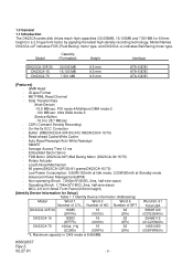
...On-the-fly ECC Correction - SMART - Non-operating Shock 7,840m/S2(800G, 2ms, half-sine wave) - 1.0 General 1.1 Introduction The DK23CA series disk drives reach high capacities (30,005MB, 15,103MB and 7,501MB for Setup] Table 1.1 Identify Device information (Addressing) Model Word 1 Word 3 Word 6 Word 60Ŋ61 Number..., and DK23CA-xx indicates Ball Bering motor type. Auto Read Reassign/Auto Write Reassign - Model Capacity (Formatted) Height Interface DK23CA-30F/30 DK23CA-15 DK23CA-75 30,005 MB 15,103 MB 7,501 MB 9.5 mm 9.5 mm 9.5 mm ATA-5(IDE) ATA-5(IDE) ATA-5(IDE) [Features] ...
...On-the-fly ECC Correction - SMART - Non-operating Shock 7,840m/S2(800G, 2ms, half-sine wave) - 1.0 General 1.1 Introduction The DK23CA series disk drives reach high capacities (30,005MB, 15,103MB and 7,501MB for Setup] Table 1.1 Identify Device information (Addressing) Model Word 1 Word 3 Word 6 Word 60Ŋ61 Number..., and DK23CA-xx indicates Ball Bering motor type. Auto Read Reassign/Auto Write Reassign - Model Capacity (Formatted) Height Interface DK23CA-30F/30 DK23CA-15 DK23CA-75 30,005 MB 15,103 MB 7,501 MB 9.5 mm 9.5 mm 9.5 mm ATA-5(IDE) ATA-5(IDE) ATA-5(IDE) [Features] ...
Specifications
Page 13
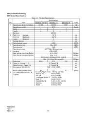
... Standby 0.050 A(0.25W) - Ready *2 7 DimensionsʢWʷHʷD) DK23CA-30F/30 DK23CA-15 DK23CA-75 30,005 15,103 7,501 512 2 1 1 4 2 1 28,134 12 *1 24 ...91 +5v ʶ 5% Ripple noise 100mvp-p or less - Item 1 Capacity per drive (Formatted) Capacity per sector Disks Heads Cylinders 2 Seek time Average (Nominal Maximum value) ...Minimum 3 Average latency Disk rotational speed 4 Recording density Track density Recording method 5 Interface Data transfer rate (Disk-Buffer) Data transfer rate (Host-Buffer) Buffer size 6 Power on -...
... Standby 0.050 A(0.25W) - Ready *2 7 DimensionsʢWʷHʷD) DK23CA-30F/30 DK23CA-15 DK23CA-75 30,005 15,103 7,501 512 2 1 1 4 2 1 28,134 12 *1 24 ...91 +5v ʶ 5% Ripple noise 100mvp-p or less - Item 1 Capacity per drive (Formatted) Capacity per sector Disks Heads Cylinders 2 Seek time Average (Nominal Maximum value) ...Minimum 3 Average latency Disk rotational speed 4 Recording density Track density Recording method 5 Interface Data transfer rate (Disk-Buffer) Data transfer rate (Host-Buffer) Buffer size 6 Power on -...
Specifications
Page 54
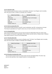
The Sector Count Register sets the standby timer value. Sector Count Value SC = 0 0 By the power on default, the Standby timer is disabled. 6.3.2.6.4 Idle [97h, E3h] This command causes the device to enter to the Idle Mode.
The Sector Count Register sets the standby timer value. Sector Count Value SC = 0 0 By the power on default, the Standby timer is disabled. 6.3.2.6.4 Idle [97h, E3h] This command causes the device to enter to the Idle Mode.

Specifications
Page 88
... 6.4.1 Data Transfer Timing Figures 6-4, 6-5, 6-6 and 6-7 show the timing for asserting interface signals for transferring 16-bit and 8-bit data. Data Setup 20 t4 DIOW- Data Hold 10 t5 DIOR- Negation (MAX) t9 DIOR-/DIOW- t3 t4 ... DD0-15(16 bit) or DD0-7(8 bit) SYMBOL Description MIN(ns) t0 Cycle Time 120 t1 Address Valid to Address Valid Hold 10 MAX(ns) 30 40 30 K6602637 Rev.3 02.27.01 - 88 - Recovery 25 t3 DIOW- Assertion(MAX) t8 Addr Valid To IOCS16- Data Setup 20 t6 DIOR- Data Hold...
... 6.4.1 Data Transfer Timing Figures 6-4, 6-5, 6-6 and 6-7 show the timing for asserting interface signals for transferring 16-bit and 8-bit data. Data Setup 20 t4 DIOW- Data Hold 10 t5 DIOR- Negation (MAX) t9 DIOR-/DIOW- t3 t4 ... DD0-15(16 bit) or DD0-7(8 bit) SYMBOL Description MIN(ns) t0 Cycle Time 120 t1 Address Valid to Address Valid Hold 10 MAX(ns) 30 40 30 K6602637 Rev.3 02.27.01 - 88 - Recovery 25 t3 DIOW- Assertion(MAX) t8 Addr Valid To IOCS16- Data Setup 20 t6 DIOR- Data Hold...