
Specifications
Page 6
... Setting(DRIVE 0/DRIVE 1) 4.4 Dimensions 5.0 Packing and Handling 5.1 Packing 5.2 Handling 6.0 Interface 6.1 Power Interface 6.2 Physical Interface 6.2.1 Connector 6.2.2 Connector Pin Assignment 6.2.3 Description of the Interface Signals 6.3 Logical Interface 6.3.1 I/O Registers 6.3.1.1 Data Register 6.3.1.2 Error Register 6.3.1.3 Features Register 6.3.1.4 Sector Count Register 6.3.1.5 Sector Number Register 6.3.1.6 Cylinder Low Register 6.3.1.7 Cylinder High Register 6.3.1.8 Device/Head Register 6.3.1.9 Status Register 6.3.1.10 Command Register 6.3.1.11 Alternate...
... Setting(DRIVE 0/DRIVE 1) 4.4 Dimensions 5.0 Packing and Handling 5.1 Packing 5.2 Handling 6.0 Interface 6.1 Power Interface 6.2 Physical Interface 6.2.1 Connector 6.2.2 Connector Pin Assignment 6.2.3 Description of the Interface Signals 6.3 Logical Interface 6.3.1 I/O Registers 6.3.1.1 Data Register 6.3.1.2 Error Register 6.3.1.3 Features Register 6.3.1.4 Sector Count Register 6.3.1.5 Sector Number Register 6.3.1.6 Cylinder Low Register 6.3.1.7 Cylinder High Register 6.3.1.8 Device/Head Register 6.3.1.9 Status Register 6.3.1.10 Command Register 6.3.1.11 Alternate...

Specifications
Page 7
... [EFh] 48 6.3.2.5.6 Set Multiple Mode [C6h] 49 6.3.2.5.7 Execute Device Diagnostic [90h] 49 6.3.2.5.8 Flush Cache [E7h] 50 6.3.2.6 Power Commands 51 6.3.2.6.1 Power Management 51 6.3.2.6.2 Advanced Power Management 52 6.3.2.6.3 Check Power Mode [98h, E5h] 53 6.3.2.6.4 Idle [97h, E3h] 54...10 SMART Enable/Disable Automatic Off-line [B0h, Sub DBh 61 6.3.2.8.11 SMART Execute Off-line Immediate [B0h, Sub D4h 62 K6602637 Rev.3 02.27.01 - 7 - 6.3.2 Command 35 6.3.2.1 Command Summary 35 6.3.2.2 Command BSY Timing 36 6.3.2.3 PIO Data In Commands...
... [EFh] 48 6.3.2.5.6 Set Multiple Mode [C6h] 49 6.3.2.5.7 Execute Device Diagnostic [90h] 49 6.3.2.5.8 Flush Cache [E7h] 50 6.3.2.6 Power Commands 51 6.3.2.6.1 Power Management 51 6.3.2.6.2 Advanced Power Management 52 6.3.2.6.3 Check Power Mode [98h, E5h] 53 6.3.2.6.4 Idle [97h, E3h] 54...10 SMART Enable/Disable Automatic Off-line [B0h, Sub DBh 61 6.3.2.8.11 SMART Execute Off-line Immediate [B0h, Sub D4h 62 K6602637 Rev.3 02.27.01 - 7 - 6.3.2 Command 35 6.3.2.1 Command Summary 35 6.3.2.2 Command BSY Timing 36 6.3.2.3 PIO Data In Commands...
Specifications
Page 8
... Max Security Extension 79 6.3.2.10.2 Address Offset Feature 80 6.3.2.10.3 Read Max Address Command [F8h] 82 6.3.2.10.4 Set Max Address Command [F9h, Sub 00h] 83 6.3.2.10.5 Set Max Set Password Command [F9h, Sub 01h] 85 6.3.2.10.6 Set Max Lock Command [F9h, Sub 02h] 85 6.3.2.10.7 Set Max Unlock Command [F9h, Sub 03h] 86 6.3.2.10.8 Set Max Freeze Lock Command [F9h, Sub 04h] 86...
... Max Security Extension 79 6.3.2.10.2 Address Offset Feature 80 6.3.2.10.3 Read Max Address Command [F8h] 82 6.3.2.10.4 Set Max Address Command [F9h, Sub 00h] 83 6.3.2.10.5 Set Max Set Password Command [F9h, Sub 01h] 85 6.3.2.10.6 Set Max Lock Command [F9h, Sub 02h] 85 6.3.2.10.7 Set Max Unlock Command [F9h, Sub 03h] 86 6.3.2.10.8 Set Max Freeze Lock Command [F9h, Sub 04h] 86...
Specifications
Page 17
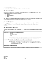
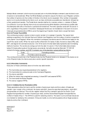
...not include an emergency unload as Soft Reset, Flush Cache command or Check Power Mode command does not unload the heads. Soft Reset does not unload the heads from DK23CA-xx. [Sequence #2]: Check the Status Register, and wait the command complete. Standby - Sleep Note: Such as explained in Sec.... 3.4.2. 3.4.2 Emergency Unload The emergency unload is occurred by the software control after power off the drive Above sequence is limited to...
...not include an emergency unload as Soft Reset, Flush Cache command or Check Power Mode command does not unload the heads. Soft Reset does not unload the heads from DK23CA-xx. [Sequence #2]: Check the Status Register, and wait the command complete. Standby - Sleep Note: Such as explained in Sec.... 3.4.2. 3.4.2 Emergency Unload The emergency unload is occurred by the software control after power off the drive Above sequence is limited to...
Specifications
Page 29
... 31 IOCS16- 32 DA0-2 PDIAG-:CBLID- (*1) 33,35,36 34 I/O type O O I I This device chip selection signal is used to select the Command Block Registers from the host system. 38 I /O Table 6.2 Signal List(2/3) Description This is an interrupt signal for all devices on or hardware reset sequence. ...system. This signal is used to select the Control Block Registers from the host system. The host may sample CBLID- after the first command following steps: a) The host shall wait until the power on or hardware reset sequence is complete for the host system. conductor cable ...
... 31 IOCS16- 32 DA0-2 PDIAG-:CBLID- (*1) 33,35,36 34 I/O type O O I I This device chip selection signal is used to select the Command Block Registers from the host system. 38 I /O Table 6.2 Signal List(2/3) Description This is an interrupt signal for all devices on or hardware reset sequence. ...system. This signal is used to select the Control Block Registers from the host system. The host may sample CBLID- after the first command following steps: a) The host shall wait until the power on or hardware reset sequence is complete for the host system. conductor cable ...

Specifications
Page 30
...High level +2.0V to Vcc+0.5V Low level -0.5V to +0.8V (2) Output signal High level +2.4V to transfer data. See Sec. 4.3 " Drive Address Setting (Drive 0/Drive 1)" for DMA data transfers between host and device, when it may cause factional degradations or some errors. Table 6.2 Signal List(3/3) Description This signal ...or an open circuit Low level +0.4V or less (IOL=2mA), +0.5V or less (IOL=12mA) Note) The I - Upon receipt of a command from the host, the device does not assert this signal, used for the detail. The device shall assert this signal. Signal name DASP-
...High level +2.0V to Vcc+0.5V Low level -0.5V to +0.8V (2) Output signal High level +2.4V to transfer data. See Sec. 4.3 " Drive Address Setting (Drive 0/Drive 1)" for DMA data transfers between host and device, when it may cause factional degradations or some errors. Table 6.2 Signal List(3/3) Description This signal ...or an open circuit Low level +0.4V or less (IOL=2mA), +0.5V or less (IOL=12mA) Note) The I - Upon receipt of a command from the host, the device does not assert this signal, used for the detail. The device shall assert this signal. Signal name DASP-

Specifications
Page 31
... 1 1 Sector Number Sector Number 0 1 1 0 0 Cyl Low Cyl Low 0 1 1 0 1 Cyl High Cyl High 0 1 1 1 0 Device/Head Device/Head 0 1 1 1 1 Status Command Control Block Registers 1 0 1 1 0 Alt. Table 6.3 Register List Addresses Functions CS0- 6.3 Logical Interface 6.3.1 I/O Registers Communication between the HDD's data buffer and the host. 6.3.1.2 Error register This... register stores device status when the last command has been completed or diagnostic codes when a self-diagnostic process has been completed. The...
... 1 1 Sector Number Sector Number 0 1 1 0 0 Cyl Low Cyl Low 0 1 1 0 1 Cyl High Cyl High 0 1 1 1 0 Device/Head Device/Head 0 1 1 1 1 Status Command Control Block Registers 1 0 1 1 0 Alt. Table 6.3 Register List Addresses Functions CS0- 6.3 Logical Interface 6.3.1 I/O Registers Communication between the HDD's data buffer and the host. 6.3.1.2 Error register This... register stores device status when the last command has been completed or diagnostic codes when a self-diagnostic process has been completed. The...

Specifications
Page 32
...Register This register contains the starting sector number for any disk access. d) IDNF (ID Not Found): This bit indicates that the command has been executed successfully. f) ICRC(Interface CRC Error): This bit indicates that an uncorrectable error has occurred. this register contains Bits... 23-16 of the starting cylinder address for Multiword DMA transfers. 6.3.1.3 Features Register By combining with the Set Features command, this register indicates the number of sectors per track. K6602637 Rev.3 02.27.01 - 32 - For more information on a...
...Register This register contains the starting sector number for any disk access. d) IDNF (ID Not Found): This bit indicates that the command has been executed successfully. f) ICRC(Interface CRC Error): This bit indicates that an uncorrectable error has occurred. this register contains Bits... 23-16 of the starting cylinder address for Multiword DMA transfers. 6.3.1.3 Features Register By combining with the Set Features command, this register indicates the number of sectors per track. K6602637 Rev.3 02.27.01 - 32 - For more information on a...

Specifications
Page 33
...indicates that an error occurs during a Write operation. If an error has occurred, the value of the Status Register are returned. 6.3.1.10 Command Register The command code is not changed until the host reads the Status register. K6602637 Rev.3 02.27.01 - 33 - If BSY=1, no other... is cleared when the power is ready to the description of device and head selected. HS3 is 1,the host cannot access the Command Block Registers. For more information, refer to transfer data between the host and the device. 6.3.1.8 Device/Head Register This register has...
...indicates that an error occurs during a Write operation. If an error has occurred, the value of the Status Register are returned. 6.3.1.10 Command Register The command code is not changed until the host reads the Status register. K6602637 Rev.3 02.27.01 - 33 - If BSY=1, no other... is cleared when the power is ready to the description of device and head selected. HS3 is 1,the host cannot access the Command Block Registers. For more information, refer to transfer data between the host and the device. 6.3.1.8 Device/Head Register This register has...

Specifications
Page 35
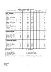
... V V V V Read Multiple PI 1 C4h V V V V Read DMA DM 1 C8h, C9h V V V V Read Verify ND 1 40h, 41h V V V V Write Commands Write Buffer PO 2 E8h D Write Sectors PO 2 30h, 31h V V V V Write Long PO 2 32h, 33h V V V V Write Multiple PO 3 C5h V V V ...V Write DMA DM 3 CAh,CBh V V V V Format Track PO 2 50h V V V Flush Cache ND 1 E7h D Seek Commands Recalibrate ND 1 1Xh D Seek ND 1 7Xh V V V Mode Set/Check, Diagnostic Execute Device Diagnostic ND 1 90h D Initialize Device Parameters ND 1 91h V...
... V V V V Read Multiple PI 1 C4h V V V V Read DMA DM 1 C8h, C9h V V V V Read Verify ND 1 40h, 41h V V V V Write Commands Write Buffer PO 2 E8h D Write Sectors PO 2 30h, 31h V V V V Write Long PO 2 32h, 33h V V V V Write Multiple PO 3 C5h V V V ...V Write DMA DM 3 CAh,CBh V V V V Format Track PO 2 50h V V V Flush Cache ND 1 E7h D Seek Commands Recalibrate ND 1 1Xh D Seek ND 1 7Xh V V V Mode Set/Check, Diagnostic Execute Device Diagnostic ND 1 90h D Initialize Device Parameters ND 1 91h V...
Specifications
Page 36
... D4h V D Immediate SMART Read Log Sector PI 1 B0h D5h V V V D SMART Write Log Sector PO 3 B0h D6h V V V D Security Commands Security Disable Password PO 3 F6h D Security Erase Prepare ND 1 F3h D Security Erase Unit PO 3 F4h D Security Freeze Lock ND 1 F5h D Security... Set Password PO 3 F1h D Security Unlock PO 3 F2h D Protected Area Commands Read Max Address ND 1 F8h D Set Max Address ND 1 F9h 00h V V V D Set Max Set Password PO 3 F9h 01h D Set ...
... D4h V D Immediate SMART Read Log Sector PI 1 B0h D5h V V V D SMART Write Log Sector PO 3 B0h D6h V V V D Security Commands Security Disable Password PO 3 F6h D Security Erase Prepare ND 1 F3h D Security Erase Unit PO 3 F4h D Security Freeze Lock ND 1 F5h D Security... Set Password PO 3 F1h D Security Unlock PO 3 F2h D Protected Area Commands Read Max Address ND 1 F8h D Set Max Address ND 1 F9h 00h V V V D Set Max Set Password PO 3 F9h 01h D Set ...

Specifications
Page 37
...DRQ and clears BSY prior to asserting INTRQ. 5) After detecting INTRQ, the host reads the Status Register, then reads one sector (block) of command acceptance all predicated on the fact that the BSY transition is too short for data transfer. 4) When a sector(block) of data is repeated ...any required parameters to the Features, Sector Count, Sector Number, Cylinder Low, Cylinder High, and Device/Head registers. 2) The host writes the command code to the Command Register. 3) The device sets BSY and prepares for BSY=1 to the Status Register being read, the device negates INTRQ. 6) The device ...
...DRQ and clears BSY prior to asserting INTRQ. 5) After detecting INTRQ, the host reads the Status Register, then reads one sector (block) of command acceptance all predicated on the fact that the BSY transition is too short for data transfer. 4) When a sector(block) of data is repeated ...any required parameters to the Features, Sector Count, Sector Number, Cylinder Low, Cylinder High, and Device/Head registers. 2) The host writes the command code to the Command Register. 3) The device sets BSY and prepares for BSY=1 to the Status Register being read, the device negates INTRQ. 6) The device ...
Specifications
Page 38
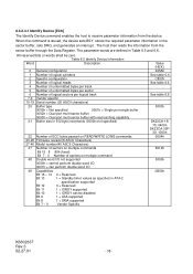
... Vendor Specific Value (HEX.) 045Ah See table 6.6 C837h See table 6.6 See table 6.6 0003h DK23CA-15/ 75: 0400h DK23CA-30F/ 30: 1000h 0004h 8010h 0000h 0B00h K6602637 Rev.3 02.27.01 - 38 - When the command is issued, the device sets BSY, stores the required parameter information in Table 6.5 and 6.6. ... Number of unformatted bytes per track 5 Number of unformatted bytes per sector 6 Number of logical sectors per logical track 7-9 Vendor specific 10-19 Serial number (20 ASCII characters) 20 Buffer type 0000h = Not specified 0001h = Single port single buffer 0002h = Dual port ...
... Vendor Specific Value (HEX.) 045Ah See table 6.6 C837h See table 6.6 See table 6.6 0003h DK23CA-15/ 75: 0400h DK23CA-30F/ 30: 1000h 0004h 8010h 0000h 0B00h K6602637 Rev.3 02.27.01 - 38 - When the command is issued, the device sets BSY, stores the required parameter information in Table 6.5 and 6.6. ... Number of unformatted bytes per track 5 Number of unformatted bytes per sector 6 Number of logical sectors per logical track 7-9 Vendor specific 10-19 Serial number (20 ASCII characters) 20 Buffer type 0000h = Not specified 0001h = Single port single buffer 0002h = Dual port ...
Specifications
Page 39
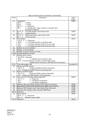
... 0 (fixed) Bit 14 1 (fixed) Bit 13 - 1 0 = Reserved Bit 0 1 = Standby timer value is valid Bit 7 - 0Current setting for number of current sectors per interrupt on R/W MULTIPLE command Total addressable LBA Single word DMA transfer Bit 15 - 8 Single word DMA transfer mode active Bit 7 - 0Single word DMA transfer mode supported Multi-word DMA...
... 0 (fixed) Bit 14 1 (fixed) Bit 13 - 1 0 = Reserved Bit 0 1 = Standby timer value is valid Bit 7 - 0Current setting for number of current sectors per interrupt on R/W MULTIPLE command Total addressable LBA Single word DMA transfer Bit 15 - 8 Single word DMA transfer mode active Bit 7 - 0Single word DMA transfer mode supported Multi-word DMA...
Specifications
Page 40
... 1 1 = Supports ATA-1 Bit 0 Reserved 81 ATA Interface Minor Version Number 82 Command Set Supported 0000h or FFFFh = Command set notification not supported Bit 15 0 = Reserved Bit 14 1 = NOP command supported Bit 13 1 = READ BUFFER command supported Bit 12 1 = WRITE BUFFER command supported Bit 11 0 = Reserved Bit 10 1 = Host Protected Area feature set supported Bit 9 1 = DEVICE RESET...
... 1 1 = Supports ATA-1 Bit 0 Reserved 81 ATA Interface Minor Version Number 82 Command Set Supported 0000h or FFFFh = Command set notification not supported Bit 15 0 = Reserved Bit 14 1 = NOP command supported Bit 13 1 = READ BUFFER command supported Bit 12 1 = WRITE BUFFER command supported Bit 11 0 = Reserved Bit 10 1 = Host Protected Area feature set supported Bit 9 1 = DEVICE RESET...
Specifications
Page 41
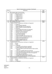
... Device Information (Continued) Description 85 Command set/feature enabled 0000h or FFFFh = Command set notification not supported Bit 15 0 = Reserved Bit 14 1 = NOP command supported Bit 13 1 = READ BUFFER command supported Bit 12 1 = WRITE BUFFER command supported Bit 11 0 = Reserved Bit 10 1 = Host Protected Area feature set supported Bit 9 1 = DEVICE RESET command supported Bit 8 1 = SERVICE interrupt enabled...
... Device Information (Continued) Description 85 Command set/feature enabled 0000h or FFFFh = Command set notification not supported Bit 15 0 = Reserved Bit 14 1 = NOP command supported Bit 13 1 = READ BUFFER command supported Bit 12 1 = WRITE BUFFER command supported Bit 11 0 = Reserved Bit 10 1 = Host Protected Area feature set supported Bit 9 1 = DEVICE RESET command supported Bit 8 1 = SERVICE interrupt enabled...

Specifications
Page 42
...15 - 14 0 = Reserved Bit 13 0 = Ultra DMA mode 5 is selected Bit 12 0 = Ultra DMA mode 4 is selected Bit 11 0 = Ultra DMA mode 3 is selected Bit 10 0 = Ultra DMA mode 2 is selected Bit 9 0 = Ultra DMA mode 1 is selected Bit 8 0 = Ultra DMA mode 0 is selected Bit 7 - 6 0 = Reserved Bit 5... below are supported 89 Time required for security erase unit completion Word 89 specifies the time required for the ENHANCED SECURITY ERASE UNIT command to completion. SECURITY ERASE UNIT completion time = value x 2[minutes] 90 Time required for enhanced security erase unit completion Word 90...
...15 - 14 0 = Reserved Bit 13 0 = Ultra DMA mode 5 is selected Bit 12 0 = Ultra DMA mode 4 is selected Bit 11 0 = Ultra DMA mode 3 is selected Bit 10 0 = Ultra DMA mode 2 is selected Bit 9 0 = Ultra DMA mode 1 is selected Bit 8 0 = Ultra DMA mode 0 is selected Bit 7 - 6 0 = Reserved Bit 5... below are supported 89 Time required for security erase unit completion Word 89 specifies the time required for the ENHANCED SECURITY ERASE UNIT command to completion. SECURITY ERASE UNIT completion time = value x 2[minutes] 90 Time required for enhanced security erase unit completion Word 90...

Specifications
Page 45
...in the Sector Number Register. An implied seek is done if needed, after transfer of the last sector read. When the Read Multiple command is issued, the Sector Count Register contains the number of sectors (not the number of {Sector Count/Sector Count per Block}. Interrupts ... the block or partial block transfer, but on each block or partial block. Subsequent blocks or partial blocks are supported. At command completion, the Command Block Registers contain the cylinder, head, and sector numbers of the block that it normally would, including transfer of the desired sector...
...in the Sector Number Register. An implied seek is done if needed, after transfer of the last sector read. When the Read Multiple command is issued, the Sector Count Register contains the number of sectors (not the number of {Sector Count/Sector Count per Block}. Interrupts ... the block or partial block transfer, but on each block or partial block. Subsequent blocks or partial blocks are supported. At command completion, the Command Block Registers contain the cylinder, head, and sector numbers of the block that it normally would, including transfer of the desired sector...
Specifications
Page 46
...device. If the target sector is posted, but on each sector. The number of sectors defined by the ECU bytes. 6.3.2.4 PIO Data Out Commands Execution includes the transfer of one or more than one sector block of data to the Data Register. 5) The device clears DRQ and sets BSY... any required parameters to the Features, Sector Count, Sector Number, Cylinder Low, Cylinder High, and Device/Head Registers. 2) The host writes the command code to the Command Register. 3) The device sets the DRQ when it gets ready to accept the first sector(block) of data. 4) The host writes one sector...
...device. If the target sector is posted, but on each sector. The number of sectors defined by the ECU bytes. 6.3.2.4 PIO Data Out Commands Execution includes the transfer of one or more than one sector block of data to the Data Register. 5) The device clears DRQ and sets BSY... any required parameters to the Features, Sector Count, Sector Number, Cylinder Low, Cylinder High, and Device/Head Registers. 2) The host writes the command code to the Command Register. 3) The device sets the DRQ when it gets ready to accept the first sector(block) of data. 4) The host writes one sector...
Specifications
Page 47
... of heads minus 1. One 16-bit word of format table data represents each block, except first block. 6.3.2.4.5 Format Track [50h] This command provides a means to reassign it clears BSY and asserts INTRQ. 5) The host reads the Status Register. 6) The device negates INTRQ. 6.3.2.5.1...posted until an illegal access is specified in the Physical mode, the device executes a vendor specific operation. 6.3.2.5 Non-Data Commands Execution of the command, the device sets BSY, saves the specified parameters, clears BSY, and generates an interrupt. The logical track address is ...
... of heads minus 1. One 16-bit word of format table data represents each block, except first block. 6.3.2.4.5 Format Track [50h] This command provides a means to reassign it clears BSY and asserts INTRQ. 5) The host reads the Status Register. 6) The device negates INTRQ. 6.3.2.5.1...posted until an illegal access is specified in the Physical mode, the device executes a vendor specific operation. 6.3.2.5 Non-Data Commands Execution of the command, the device sets BSY, saves the specified parameters, clears BSY, and generates an interrupt. The logical track address is ...