
Specifications
Page 5
...from any damage. (Keep some extra packages for the drive transportation) 22. Hitachi makes no representations or warranties with pallet to accidents such as disasters, shock damage during drive transportation to notify any damage. 23. Use original ...Hitachi does not perform data recovery. 24. Safety Instructions (Continued) Caution 19. To returning over 100 units, use original outside package with pallet or proper packaging with respect to unexpected or accidental power loss during write operation. Recorded data on should not exceed one year. 20. Prevent humidity when the drive...
...from any damage. (Keep some extra packages for the drive transportation) 22. Hitachi makes no representations or warranties with pallet to accidents such as disasters, shock damage during drive transportation to notify any damage. 23. Use original ...Hitachi does not perform data recovery. 24. Safety Instructions (Continued) Caution 19. To returning over 100 units, use original outside package with pallet or proper packaging with respect to unexpected or accidental power loss during write operation. Recorded data on should not exceed one year. 20. Prevent humidity when the drive...
Specifications
Page 6
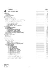
... Setting(DRIVE 0/DRIVE 1) 4.4 Dimensions 5.0 Packing and Handling 5.1 Packing 5.2 Handling 6.0 Interface 6.1 Power Interface 6.2 Physical Interface 6.2.1 Connector 6.2.2 Connector Pin Assignment 6.2.3 Description of the Interface Signals 6.3 Logical Interface 6.3.1 I/O Registers 6.3.1.1 Data Register 6.3.1.2 Error Register 6.3.1.3 Features Register 6.3.1.4 Sector Count Register 6.3.1.5 Sector Number Register 6.3.1.6 Cylinder Low Register 6.3.1.7 Cylinder High Register 6.3.1.8 Device/Head Register 6.3.1.9 Status Register 6.3.1.10 Command Register 6.3.1.11...
... Setting(DRIVE 0/DRIVE 1) 4.4 Dimensions 5.0 Packing and Handling 5.1 Packing 5.2 Handling 6.0 Interface 6.1 Power Interface 6.2 Physical Interface 6.2.1 Connector 6.2.2 Connector Pin Assignment 6.2.3 Description of the Interface Signals 6.3 Logical Interface 6.3.1 I/O Registers 6.3.1.1 Data Register 6.3.1.2 Error Register 6.3.1.3 Features Register 6.3.1.4 Sector Count Register 6.3.1.5 Sector Number Register 6.3.1.6 Cylinder Low Register 6.3.1.7 Cylinder High Register 6.3.1.8 Device/Head Register 6.3.1.9 Status Register 6.3.1.10 Command Register 6.3.1.11...
Specifications
Page 14
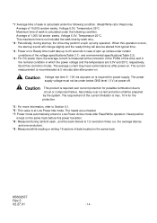
...176;C, respectively. Average of data located on to Ready time could take up to 20 seconds in which the power voltage and the temperature are unloaded. *7: Power mode ...Read/Write operation. Burst free (common mode). When this operation occurs, the start up, the drive may have some tolerance after power-on . The requirement of the current limitation is required over...the average current is calculated under the following condition. (Read/Write ratio: Read only) Average of 10,000 random seeks, Voltage 5.0V, Temperature 25°C. The current measurement is not included the ...
...176;C, respectively. Average of data located on to Ready time could take up to 20 seconds in which the power voltage and the temperature are unloaded. *7: Power mode ...Read/Write operation. Burst free (common mode). When this operation occurs, the start up, the drive may have some tolerance after power-on . The requirement of the current limitation is required over...the average current is calculated under the following condition. (Read/Write ratio: Read only) Average of 10,000 random seeks, Voltage 5.0V, Temperature 25°C. The current measurement is not included the ...
Specifications
Page 15
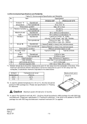
...Max. 300m/min.(3.1kpa/min.) 8 Data reliability Less than 1 non-recoverable error in HDD package box with retries and ECC) 10 E 13 bits read 9 External magnetic field 1,500 micro Tesla (DC) or less *1 : Ambient temperature should be packed in HDD package... box. Item Specification DK23CA-30F DK23CA-30/15/75 1 Ambient *1 Operational 5 to 55°C temperature Non-operational -40 to 70°C *2 Temperature gradient Max. 20°C /hour 2 Relative humidity Operational 5 to 90 % Non-operational 5 to 0°C, the drive should be packed in (*5) (...
...Max. 300m/min.(3.1kpa/min.) 8 Data reliability Less than 1 non-recoverable error in HDD package box with retries and ECC) 10 E 13 bits read 9 External magnetic field 1,500 micro Tesla (DC) or less *1 : Ambient temperature should be packed in HDD package... box. Item Specification DK23CA-30F DK23CA-30/15/75 1 Ambient *1 Operational 5 to 55°C temperature Non-operational -40 to 70°C *2 Temperature gradient Max. 20°C /hour 2 Relative humidity Operational 5 to 90 % Non-operational 5 to 0°C, the drive should be packed in (*5) (...
Specifications
Page 16
...data backup. Since reliability and product life depends on usage conditions, please consult our sales representatives or application engineers if the drive may be less than 20MHz). This number includes Standby, Sleep and power-on and loading operation. For non-operating rotational ... Max. 100,000 times. The spindle motor is recommended within twelve hours' power on hours (POH) : Less than 20% of the drive. The grounding current should be measured through 50 ohm resistor. -External Magnetic Field : Within specifications given in Table 3.1 "Principal Specifications...
...data backup. Since reliability and product life depends on usage conditions, please consult our sales representatives or application engineers if the drive may be less than 20MHz). This number includes Standby, Sleep and power-on and loading operation. For non-operating rotational ... Max. 100,000 times. The spindle motor is recommended within twelve hours' power on hours (POH) : Less than 20% of the drive. The grounding current should be measured through 50 ohm resistor. -External Magnetic Field : Within specifications given in Table 3.1 "Principal Specifications...
Specifications
Page 17
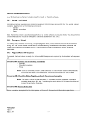
...sec by the software control after power off , Suspend and Hibernation operations. Soft Reset does not unload the heads from DK23CA-xx. [Sequence #2]: Check the Status Register, and wait the command complete. Sleep Note: Such as explained in Sec... power down, and is required for the Host system at Power off , the heads are limited to maximum 20,000 times during Idle mode. Standby - Note: The head is unload by the sequence #1 command, and the...should be performed by the Host side. [Sequence #3]: Power off the drive Above sequence is limited to maximum 300,000 times during HDD life.
...sec by the software control after power off , Suspend and Hibernation operations. Soft Reset does not unload the heads from DK23CA-xx. [Sequence #2]: Check the Status Register, and wait the command complete. Sleep Note: Such as explained in Sec... power down, and is required for the Host system at Power off , the heads are limited to maximum 20,000 times during Idle mode. Standby - Note: The head is unload by the sequence #1 command, and the...should be performed by the Host side. [Sequence #3]: Power off the drive Above sequence is limited to maximum 300,000 times during HDD life.
Specifications
Page 20
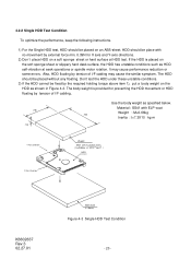
... tension of I =7.3X10⁻⁴ kg m2 ) HDD X Axis Direction K6602637 Rev.3 02.27.01 ABS-sheet (t = 5mm) Figure 4-3 Single HDD Test Condition - 20 - The HDD should be placed on the HDD as HDD self-vibration at HDD test. Also, HDD floating by the required holding torque above item... the similar symptom. If the HDD is provided for X axis and Y-axis directions. 2) Don't place HDD on the soft sponge sheet or slippery hard desk surface, the HDD has unstable conditions such as shown in Figure 4-3. 4.2.2 Single HDD Test Condition To optimize the performance, keep the following instructions....
... tension of I =7.3X10⁻⁴ kg m2 ) HDD X Axis Direction K6602637 Rev.3 02.27.01 ABS-sheet (t = 5mm) Figure 4-3 Single HDD Test Condition - 20 - The HDD should be placed on the HDD as HDD self-vibration at HDD test. Also, HDD floating by the required holding torque above item... the similar symptom. If the HDD is provided for X axis and Y-axis directions. 2) Don't place HDD on the soft sponge sheet or slippery hard desk surface, the HDD has unstable conditions such as shown in Figure 4-3. 4.2.2 Single HDD Test Condition To optimize the performance, keep the following instructions....
Specifications
Page 27
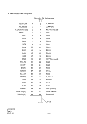
... DA0 35 CS0- 37 DASP- 39 5VDC(Logic) 41 GND(Logic) 43 B JUMPER0 D JUMPER2 F KEY(Removed) 2 GND 4 DD8 6 DD9 8 DD10 10 DD11 12 DD12 14 DD13 16 DD14 18 DD15 20 KEY(Removed) 22 GND 24 GND 26 GND 28 CSEL 30 GND 32 IOCS16- 34 PDIAG- 36 DA2 38 CS1- 40...
... DA0 35 CS0- 37 DASP- 39 5VDC(Logic) 41 GND(Logic) 43 B JUMPER0 D JUMPER2 F KEY(Removed) 2 GND 4 DD8 6 DD9 8 DD10 10 DD11 12 DD12 14 DD13 16 DD14 18 DD15 20 KEY(Removed) 22 GND 24 GND 26 GND 28 CSEL 30 GND 32 IOCS16- 34 PDIAG- 36 DA2 38 CS1- 40...

Specifications
Page 30
..., When a sequential read command is turned on. DMARQ DMACKJUMPER0,1,2 Pin 39 21 29 PIN-A,B,D I/O type I/O O I /F cable should be no longer than 50cm(20 inches) including the circuit pattern length in response to DMARQ to transfer data. At command completion, the device de-asserts this signal. If the cable... length is not within this specification, it is ready to either acknowledge that data has been accepted, or that Drive 1 is present when the power is received from the host, the device asserts this signal, used for the detail. The I/O signal levels ...
..., When a sequential read command is turned on. DMARQ DMACKJUMPER0,1,2 Pin 39 21 29 PIN-A,B,D I/O type I/O O I /F cable should be no longer than 50cm(20 inches) including the circuit pattern length in response to DMARQ to transfer data. At command completion, the device de-asserts this signal. If the cable... length is not within this specification, it is ready to either acknowledge that data has been accepted, or that Drive 1 is present when the power is received from the host, the device asserts this signal, used for the detail. The I/O signal levels ...
Specifications
Page 38
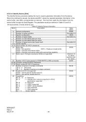
... bytes per track 5 Number of unformatted bytes per sector 6 Number of logical sectors per logical track 7-9 Vendor specific 10-19 Serial number (20 ASCII characters) 20 Buffer type 0000h = Not specified 0001h = Single port single buffer 0002h = Dual port multi-sector buffer 0003h = ... Bit 8 1 = DMA supported Bit 7 - 0 Vendor Specific Value (HEX.) 045Ah See table 6.6 C837h See table 6.6 See table 6.6 0003h DK23CA-15/ 75: 0400h DK23CA-30F/ 30: 1000h 0004h 8010h 0000h 0B00h K6602637 Rev.3 02.27.01 - 38 - 6.3.2.3.1 Identify Device [ECh] The Identify Device command enables the...
... bytes per track 5 Number of unformatted bytes per sector 6 Number of logical sectors per logical track 7-9 Vendor specific 10-19 Serial number (20 ASCII characters) 20 Buffer type 0000h = Not specified 0001h = Single port single buffer 0002h = Dual port multi-sector buffer 0003h = ... Bit 8 1 = DMA supported Bit 7 - 0 Vendor Specific Value (HEX.) 045Ah See table 6.6 C837h See table 6.6 See table 6.6 0003h DK23CA-15/ 75: 0400h DK23CA-30F/ 30: 1000h 0004h 8010h 0000h 0B00h K6602637 Rev.3 02.27.01 - 38 - 6.3.2.3.1 Identify Device [ECh] The Identify Device command enables the...
Specifications
Page 54
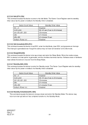
By the power on default, the Standby timer is disabled. Sector Count Value SC = 0 0 6.3.2.6.4 Idle [97h, E3h] This command causes the device to enter to the Idle Mode. The Sector Count Register sets the standby timer value.
By the power on default, the Standby timer is disabled. Sector Count Value SC = 0 0 6.3.2.6.4 Idle [97h, E3h] This command causes the device to enter to the Idle Mode. The Sector Count Register sets the standby timer value.

Specifications
Page 88
Setup 25 t2 DIOR-/DIOW- Data Hold 10 t5 DIOR- Assertion(MAX) t8 Addr Valid To IOCS16- Data Setup 20 t4 DIOW- Figure 6-4 PIO Data Transfer Timing(Mode 4) t0 Addr Valid *1 t1 t2 t9 DIOR-/DIOW- t3 t4 t5 t6 t6Z *1 Device Address consists ...) t9 DIOR-/DIOW- t2i t8 Write Data Valid *2 Read Data Valid *2 t7 IOCS16- Recovery 25 t3 DIOW- Pulse Width 70 t2i DIOR-/DIOW- Data Setup 20 t6 DIOR- Data Hold 5 t6Z DIOR- 6.4 Interface Signal Timing 6.4.1 Data Transfer Timing Figures 6-4, 6-5, 6-6 and 6-7 show the timing for asserting interface signals for transferring 16...
Setup 25 t2 DIOR-/DIOW- Data Hold 10 t5 DIOR- Assertion(MAX) t8 Addr Valid To IOCS16- Data Setup 20 t4 DIOW- Figure 6-4 PIO Data Transfer Timing(Mode 4) t0 Addr Valid *1 t1 t2 t9 DIOR-/DIOW- t3 t4 t5 t6 t6Z *1 Device Address consists ...) t9 DIOR-/DIOW- t2i t8 Write Data Valid *2 Read Data Valid *2 t7 IOCS16- Recovery 25 t3 DIOW- Pulse Width 70 t2i DIOR-/DIOW- Data Setup 20 t6 DIOR- Data Hold 5 t6Z DIOR- 6.4 Interface Signal Timing 6.4.1 Data Transfer Timing Figures 6-4, 6-5, 6-6 and 6-7 show the timing for asserting interface signals for transferring 16...
Specifications
Page 89
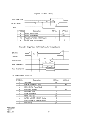
... Description t0 Cycle Time tC DMACK- Hold tS DIOR- Data Hold tG DIOW- to DMARQ delay tD DIOR- / DIOW- Setup MIN(ns) 240 120 5 35 20 0 0 tD-tE K6602637 Rev.3 02.27.01 - 89 - Data Hold tI DMACK- MAX(ns) 80 60 Figure 6-5 IORDY Timing Read Data Valid DIOR-/DIOW- Setup...
... Description t0 Cycle Time tC DMACK- Hold tS DIOR- Data Hold tG DIOW- to DMARQ delay tD DIOR- / DIOW- Setup MIN(ns) 240 120 5 35 20 0 0 tD-tE K6602637 Rev.3 02.27.01 - 89 - Data Hold tI DMACK- MAX(ns) 80 60 Figure 6-5 IORDY Timing Read Data Valid DIOR-/DIOW- Setup...
Specifications
Page 90
Data Access tF DIOR- to DIOR-/DIOW- Data Setup tH DIOW- to DMARQ Delay tM CS(1:0) valid to tristate MIN(ns) 120 70 5 20 20 10 0 5 25 25 25 MAX(ns) 50 35 25 K6602637 Rev.3 02.27.01 - 90 - Data Hold tGr DIOR- Negated Pulse Width tL DIOR- / DIOW- Data ...
Data Access tF DIOR- to DIOR-/DIOW- Data Setup tH DIOW- to DMARQ Delay tM CS(1:0) valid to tristate MIN(ns) 120 70 5 20 20 10 0 5 25 25 25 MAX(ns) 50 35 25 K6602637 Rev.3 02.27.01 - 90 - Data Hold tGr DIOR- Negated Pulse Width tL DIOR- / DIOW- Data ...

Specifications
Page 91
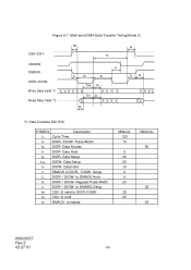
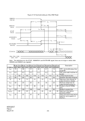
... the first transition of critical timing tACK 20 20 20 20 20 20 Setup and hold time at sender tDVH 6.2 6.2 6.2 6.2 6.2 4.8 Data valid hold times before driving IORDY tZFS 0 0 0 0 0 35 Time from data output released- 6.4.2 Ultra DMA Data Transfer Timing Figures 6-8 through 6-12 and ...MIN MAX MIN MAX MIN MAX MIN MAX tDVS 70 48 31 20 6.7 4.8 Data valid setup time at sender tFS 230 200 170 130 120 90 First strobe tUI 0 0 0 0 0 0 Unlimited interlock tAZ 10 10 10 10 10 10 Maximum time allowed for the STOP, HDMARDY and DSTROBE signal lines ...
... the first transition of critical timing tACK 20 20 20 20 20 20 Setup and hold time at sender tDVH 6.2 6.2 6.2 6.2 6.2 4.8 Data valid hold times before driving IORDY tZFS 0 0 0 0 0 35 Time from data output released- 6.4.2 Ultra DMA Data Transfer Timing Figures 6-8 through 6-12 and ...MIN MAX MIN MAX MIN MAX MIN MAX tDVS 70 48 31 20 6.7 4.8 Data valid setup time at sender tFS 230 200 170 130 120 90 First strobe tUI 0 0 0 0 0 0 Unlimited interlock tAZ 10 10 10 10 10 10 Maximum time allowed for the STOP, HDMARDY and DSTROBE signal lines ...

Specifications
Page 92
... 0(ns) Mode 1(ns) Mode 2(ns) Mode3(ns) MIN MAX MIN MAX MIN MAX MIN MAX 112 73 54 39 230 153 115 86 15 10 7 7 5 5 5 5 70 48 31 20 6.2 6.2 6.2 6.2 14.7 9.7 6.8 6.8 4.8 4.8 4.8 4.8 72.9 50.9 33.9 22.6 9.0 9.0 9.0 9.0 Mode4(ns) MIN MAX 25 57 5 5 6.7 6.2 4.8 4.8 9.5 9.0 Mode5(ns) MIN MAX 16.8 38 4 4.6 4.8 4.8 2.3 2.8 6.0 6.0 Description Cycle time allowing for asymmetry...
... 0(ns) Mode 1(ns) Mode 2(ns) Mode3(ns) MIN MAX MIN MAX MIN MAX MIN MAX 112 73 54 39 230 153 115 86 15 10 7 7 5 5 5 5 70 48 31 20 6.2 6.2 6.2 6.2 14.7 9.7 6.8 6.8 4.8 4.8 4.8 4.8 72.9 50.9 33.9 22.6 9.0 9.0 9.0 9.0 Mode4(ns) MIN MAX 25 57 5 5 6.7 6.2 4.8 4.8 9.5 9.0 Mode5(ns) MIN MAX 16.8 38 4 4.6 4.8 4.8 2.3 2.8 6.0 6.0 Description Cycle time allowing for asymmetry...

Specifications
Page 94
...0 150 0 150 0 150 0 100 0 100 0 75 Limited interlock time tMLI 20 20 20 20 20 20 Interlock time with minimum tAZ 10 10 10 10 10 10 Maximum time allowed for output drivers to release tZAH 20 20 20 20 20 20 Minimum delay time for the STOP, HDMARDY and DSTROBE signal lines are no longer in ... tACK DA0, DA1, DA2, CS0-, CS1- Note: The definitions for output drivers turning on tIORDYZ 20 20 20 20 20 20 Maximum time before releasing IORDY tACK 20 20 20 20 20 20 Setup and hold times before assertion and negation of DMACK_ tSS 50 50 50 50 50 50 Time ...
...0 150 0 150 0 150 0 100 0 100 0 75 Limited interlock time tMLI 20 20 20 20 20 20 Interlock time with minimum tAZ 10 10 10 10 10 10 Maximum time allowed for output drivers to release tZAH 20 20 20 20 20 20 Minimum delay time for the STOP, HDMARDY and DSTROBE signal lines are no longer in ... tACK DA0, DA1, DA2, CS0-, CS1- Note: The definitions for output drivers turning on tIORDYZ 20 20 20 20 20 20 Maximum time before releasing IORDY tACK 20 20 20 20 20 20 Setup and hold times before assertion and negation of DMACK_ tSS 50 50 50 50 50 50 Time ...
Specifications
Page 95
...20 20 20 20 20 20 Maximum time before releasing IORDY tACK 20 20 20 20 20 20 Setup and hold time at sender tLI 0 150 0 150 0 150 0 100 0 100 0 75 Limited interlock time tMLI 20 20 20 20 20 20 Interlock time with minimum tAZ 10 10 10 10 10 10 Maximum time allowed for output drivers to release tZAH 20 20 20 20 20 20... MAX MIN MAX MIN MAX MIN MAX MIN MAX MIN MAX tCVS 70 48 31 20 6.7 10 CRC word valid setup time at sender tCVH 6.2 6.2 6.2 6.2 6.2 10 CRC word valid hold times before assertion and negation of DMACK_ K6602637 Rev.3 02.27...
...20 20 20 20 20 20 Maximum time before releasing IORDY tACK 20 20 20 20 20 20 Setup and hold time at sender tLI 0 150 0 150 0 150 0 100 0 100 0 75 Limited interlock time tMLI 20 20 20 20 20 20 Interlock time with minimum tAZ 10 10 10 10 10 10 Maximum time allowed for output drivers to release tZAH 20 20 20 20 20 20... MAX MIN MAX MIN MAX MIN MAX MIN MAX MIN MAX tCVS 70 48 31 20 6.7 10 CRC word valid setup time at sender tCVH 6.2 6.2 6.2 6.2 6.2 10 CRC word valid hold times before assertion and negation of DMACK_ K6602637 Rev.3 02.27...
Specifications
Page 96
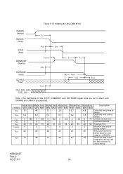
...20 70 20 70 0 0 0 tACK 20 20 20 tDZFS 70 48 31 Mode3(ns) MIN MAX 20 6.2 0 100 0 20 55 0 20 20 Mode4(ns) MIN MAX 6.7 6.2 0 100 0 20 55 0 20 6.7 Mode5(ns) Description MIN MAX 4.8 Data valid setup time at sender 4.8 Data valid hold time at sender 0 75 Limited interlock time 0 Unlimited interlock 20 50 Envelope time 0 Minimum time before driving IORDY 20... Setup and hold times before assertion and negation of DMACK_ 25 Time from data output released-to-driving until DMARQ and ...
...20 70 20 70 0 0 0 tACK 20 20 20 tDZFS 70 48 31 Mode3(ns) MIN MAX 20 6.2 0 100 0 20 55 0 20 20 Mode4(ns) MIN MAX 6.7 6.2 0 100 0 20 55 0 20 6.7 Mode5(ns) Description MIN MAX 4.8 Data valid setup time at sender 4.8 Data valid hold time at sender 0 75 Limited interlock time 0 Unlimited interlock 20 50 Envelope time 0 Minimum time before driving IORDY 20... Setup and hold times before assertion and negation of DMACK_ 25 Time from data output released-to-driving until DMARQ and ...

Specifications
Page 97
... clock variation t2CYC 230 153 115 86 57 38 Two cycle time allowing for clock variation tDS 15 10 7 7 5 4 Data setup time at recipient tDH 5 5 5 5 5 4.6 Data hold time at recipient tDVS 70 48 31 20 6.7 4.8 Data valid setup time at sender tDVH 6.2 6.2 6.2 6.2 6.2 4.8 Data valid hold time at the device until some time...
... clock variation t2CYC 230 153 115 86 57 38 Two cycle time allowing for clock variation tDS 15 10 7 7 5 4 Data setup time at recipient tDH 5 5 5 5 5 4.6 Data hold time at recipient tDVS 70 48 31 20 6.7 4.8 Data valid setup time at sender tDVH 6.2 6.2 6.2 6.2 6.2 4.8 Data valid hold time at the device until some time...