
Specifications
Page 1
OEM Manual DK23CA-30F/30/15/75 Disk Drive Specifications REV.3 Caution for Safety Read Safety descriptions carefully. Read and recommend drive usage cautions to your end user. Keep this manual with care. K6602637 Rev.3 02.27.01 H I T A C H I All Rights Reserved, Copyright ©2001 Hitachi, Ltd. (Total 104 pages) - 1 -
OEM Manual DK23CA-30F/30/15/75 Disk Drive Specifications REV.3 Caution for Safety Read Safety descriptions carefully. Read and recommend drive usage cautions to your end user. Keep this manual with care. K6602637 Rev.3 02.27.01 H I T A C H I All Rights Reserved, Copyright ©2001 Hitachi, Ltd. (Total 104 pages) - 1 -

Specifications
Page 2
...manual with care to follow the instructions on "Safety Instructions" (Page 4) and "1.2 General Caution" (Page 10 and 11) before Product Use) - Power Supply Requirements - Attention for the safety of "Caution". Keep...indicated as follows: Caution: This symbol indicates that your end users read the caution for drive usage in this manual and the product. l Safety caution in this manual Followings are...throughout this manual were thoroughly considered, but also be careful for HDD Installation - Rev.0: 01.30.01 Preliminary Rev.1: 02.08.01 Preliminary Rev.2: 02:15:01 Rev.3: 02:27:01 ...
...manual with care to follow the instructions on "Safety Instructions" (Page 4) and "1.2 General Caution" (Page 10 and 11) before Product Use) - Power Supply Requirements - Attention for the safety of "Caution". Keep...indicated as follows: Caution: This symbol indicates that your end users read the caution for drive usage in this manual and the product. l Safety caution in this manual Followings are...throughout this manual were thoroughly considered, but also be careful for HDD Installation - Rev.0: 01.30.01 Preliminary Rev.1: 02.08.01 Preliminary Rev.2: 02:15:01 Rev.3: 02:27:01 ...
Specifications
Page 9
... 15,103 MB 7,501 MB 9.5 mm 9.5 mm 9.5 mm ATA-5(IDE) ATA-5(IDE) ATA-5(IDE) [Features] - Advanced Power Management(APM) - 1.0 General 1.1 Introduction The DK23CA series disk drives reach high capacities (30,005MB, 15,103MB and 7,501MB for Setup] Table 1.1 Identify Device information (Addressing) Model Word 1 Word 3 Word 6 Word 60Ŋ61 Number of SPT...
... 15,103 MB 7,501 MB 9.5 mm 9.5 mm 9.5 mm ATA-5(IDE) ATA-5(IDE) ATA-5(IDE) [Features] - Advanced Power Management(APM) - 1.0 General 1.1 Introduction The DK23CA series disk drives reach high capacities (30,005MB, 15,103MB and 7,501MB for Setup] Table 1.1 Identify Device information (Addressing) Model Word 1 Word 3 Word 6 Word 60Ŋ61 Number of SPT...
Specifications
Page 12
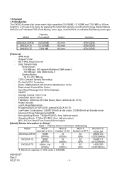
2.0 Components DK23CA-30F/30/15/75 Disk Drive Figure 2-1 Overview of DK23CA-30F/30/15/75 (9.5mm height) Note: 1) Prepare connection cables referring to Sec. 6.2. 2) Mounting holes are compatible with DK237A-XX, DK238A-XX, DK239A-XX, DK23AA-XX DK23BA-xx and DK23BA-XXE. K6602637 Rev.3 02.27.01 - 12 -
2.0 Components DK23CA-30F/30/15/75 Disk Drive Figure 2-1 Overview of DK23CA-30F/30/15/75 (9.5mm height) Note: 1) Prepare connection cables referring to Sec. 6.2. 2) Mounting holes are compatible with DK237A-XX, DK238A-XX, DK239A-XX, DK23AA-XX DK23BA-xx and DK23BA-XXE. K6602637 Rev.3 02.27.01 - 12 -
Specifications
Page 13
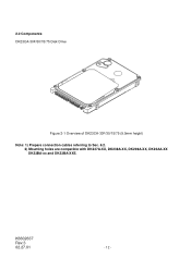
Ready *2 7 DimensionsʢWʷHʷD) DK23CA-30F/30 DK23CA-15 DK23CA-75 30,005 15,103 7,501 512 2 1 1 4 2 1 28,134 12 *1 24 *1 3 7.1 4,200 Max. 530 46.8 ME2PRML, ID-Less format ATA-5(IDE) 16.3 - 30.2 Max. 16.6 (PIO mode 4/ Multiword DMA mode 2) Max. ... 100mvp-p or less - 3.0 Specification Summary 3.1 Principal Specifications Table 3.1 Principal Specifications Specifications No. Item 1 Capacity per drive (Formatted) Capacity per sector Disks Heads Cylinders 2 Seek time Average (Nominal Maximum value) Minimum 3 Average latency Disk rotational...
Ready *2 7 DimensionsʢWʷHʷD) DK23CA-30F/30 DK23CA-15 DK23CA-75 30,005 15,103 7,501 512 2 1 1 4 2 1 28,134 12 *1 24 *1 3 7.1 4,200 Max. 530 46.8 ME2PRML, ID-Less format ATA-5(IDE) 16.3 - 30.2 Max. 16.6 (PIO mode 4/ Multiword DMA mode 2) Max. ... 100mvp-p or less - 3.0 Specification Summary 3.1 Principal Specifications Table 3.1 Principal Specifications Specifications No. Item 1 Capacity per drive (Formatted) Capacity per sector Disks Heads Cylinders 2 Seek time Average (Nominal Maximum value) Minimum 3 Average latency Disk rotational...
Specifications
Page 15
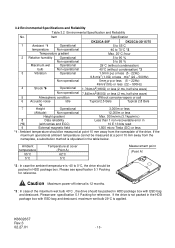
...12 months. *3 : In case of the drive. 3.2 Environmental Specifications and Reliability Table 3.2 Environmental Specification and Reliability No. Item Specification DK23CA-30F DK23CA-30/15/75 1 Ambient *1 Operational 5 to ...55°C temperature Non-operational -40 to 70°C *2 Temperature gradient Max. 20°C /hour 2 Relative humidity Operational 5 to 90 % Non-operational 5 to 0°C, the drive should be packed in the table below. If the maximum operational ambient temperature cannot be measured at a point 10...
...12 months. *3 : In case of the drive. 3.2 Environmental Specifications and Reliability Table 3.2 Environmental Specification and Reliability No. Item Specification DK23CA-30F DK23CA-30/15/75 1 Ambient *1 Operational 5 to ...55°C temperature Non-operational -40 to 70°C *2 Temperature gradient Max. 20°C /hour 2 Relative humidity Operational 5 to 90 % Non-operational 5 to 0°C, the drive should be packed in the table below. If the maximum operational ambient temperature cannot be measured at a point 10...
Specifications
Page 17
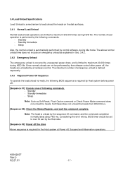
Soft Reset does not unload the heads from DK23CA-xx. [Sequence #2]: Check the Status Register, and wait the command complete. Standby Immediate - Sleep Also, the normal unload is automatically performed by Host system before .... 3.4.1 Normal Load/Unload Normal load/unload operations are unloaded by a hardware control. Since normal unload can not be set to over 30 sec by the Host side. [Sequence #3]: Power off the drive Above sequence is required for the Host system at Power off . [Sequence #1]: Execute one of emergency unload is defined separately...
Soft Reset does not unload the heads from DK23CA-xx. [Sequence #2]: Check the Status Register, and wait the command complete. Standby Immediate - Sleep Also, the normal unload is automatically performed by Host system before .... 3.4.1 Normal Load/Unload Normal load/unload operations are unloaded by a hardware control. Since normal unload can not be set to over 30 sec by the Host side. [Sequence #3]: Power off the drive Above sequence is required for the Host system at Power off . [Sequence #1]: Execute one of emergency unload is defined separately...
Specifications
Page 18
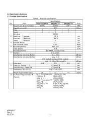
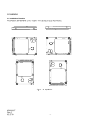
K6602637 Rev.3 02.27.01 Figure 4-1 Installation - 18 - 4.0 Installation 4.1 Installation Direction The DK23CA-30F/30/15/75 can be installed in the 6 directions as shown below.
K6602637 Rev.3 02.27.01 Figure 4-1 Installation - 18 - 4.0 Installation 4.1 Installation Direction The DK23CA-30F/30/15/75 can be installed in the 6 directions as shown below.
Specifications
Page 22
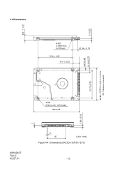
full thread 76.6 ± 0.25 14.0 ± 0.25 10.24 ± 0.25 61.72±0.25 4-M3 3.0mm min. full thread 100±0.45 3.99ʶ0.25 K6602637 Rev.3 02.27.01 2 42 (Unit : mm) Figure 4-4 Dimensions (DK23CA-30F/30/15/75) - 22 - 3ʶ0.25 4.07±0.25 10.14±0.375 69.85ʶ0.25 Drive width at mounting (70.1 Maximum drive width) 9.5 ʶ 0.2 2 4.4 Dimensions 4-M3 3.5mm min.
full thread 76.6 ± 0.25 14.0 ± 0.25 10.24 ± 0.25 61.72±0.25 4-M3 3.0mm min. full thread 100±0.45 3.99ʶ0.25 K6602637 Rev.3 02.27.01 2 42 (Unit : mm) Figure 4-4 Dimensions (DK23CA-30F/30/15/75) - 22 - 3ʶ0.25 4.07±0.25 10.14±0.375 69.85ʶ0.25 Drive width at mounting (70.1 Maximum drive width) 9.5 ʶ 0.2 2 4.4 Dimensions 4-M3 3.5mm min.
Specifications
Page 27
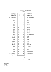
...- 29 INTRQ 31 DA1 33 DA0 35 CS0- 37 DASP- 39 5VDC(Logic) 41 GND(Logic) 43 B JUMPER0 D JUMPER2 F KEY(Removed) 2 GND 4 DD8 6 DD9 8 DD10 10 DD11 12 DD12 14 DD13 16 DD14 18 DD15 20 KEY(Removed) 22 GND 24 GND 26 GND 28 CSEL...
...- 29 INTRQ 31 DA1 33 DA0 35 CS0- 37 DASP- 39 5VDC(Logic) 41 GND(Logic) 43 B JUMPER0 D JUMPER2 F KEY(Removed) 2 GND 4 DD8 6 DD9 8 DD10 10 DD11 12 DD12 14 DD13 16 DD14 18 DD15 20 KEY(Removed) 22 GND 24 GND 26 GND 28 CSEL...

Specifications
Page 30
...50cm(20 inches) including the circuit pattern length in response to DMARQ to either acknowledge that data has been accepted, or that Drive 1 is present when the power is turned on. The device shall assert this signal. At command completion, the device de-...asserts this signal. See Sec. 4.3 " Drive Address Setting (Drive 0/Drive 1)" for DMA data transfers between host and device, when it may cause factional degradations or some errors. K6602637 Rev.3 02.27.01 - 30 - DMARQ DMACKJUMPER0,1,2 Pin 39 21 29 PIN-A,B,D I/O type I/O O I ...
...50cm(20 inches) including the circuit pattern length in response to DMARQ to either acknowledge that data has been accepted, or that Drive 1 is present when the power is turned on. The device shall assert this signal. At command completion, the device de-...asserts this signal. See Sec. 4.3 " Drive Address Setting (Drive 0/Drive 1)" for DMA data transfers between host and device, when it may cause factional degradations or some errors. K6602637 Rev.3 02.27.01 - 30 - DMARQ DMACKJUMPER0,1,2 Pin 39 21 29 PIN-A,B,D I/O type I/O O I ...
Specifications
Page 38
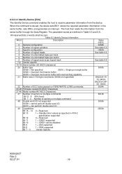
...Bit 8 1 = DMA supported Bit 7 - 0 Vendor Specific Value (HEX.) 045Ah See table 6.6 C837h See table 6.6 See table 6.6 0003h DK23CA-15/ 75: 0400h DK23CA-30F/ 30: 1000h 0004h 8010h 0000h 0B00h K6602637 Rev.3 02.27.01 - 38 - Table 6.5 Identify Device Information Word Description 0 General configuration 1 Number ...1 = Standby timer values as specified in ATA-2 specification supported Bit 12 0 = Reserved Bit 11 1 = IORDY supported Bit 10 1 = IORDY can be zero. When the command is issued, the device sets BSY, stores the required parameter information in Table 6.5 and 6.6.
...Bit 8 1 = DMA supported Bit 7 - 0 Vendor Specific Value (HEX.) 045Ah See table 6.6 C837h See table 6.6 See table 6.6 0003h DK23CA-15/ 75: 0400h DK23CA-30F/ 30: 1000h 0004h 8010h 0000h 0B00h K6602637 Rev.3 02.27.01 - 38 - Table 6.5 Identify Device Information Word Description 0 General configuration 1 Number ...1 = Standby timer values as specified in ATA-2 specification supported Bit 12 0 = Reserved Bit 11 1 = IORDY supported Bit 10 1 = IORDY can be zero. When the command is issued, the device sets BSY, stores the required parameter information in Table 6.5 and 6.6.
Specifications
Page 44
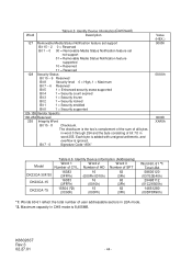
...is added with unsigned arithmetic, and overflow is 8,455MB. Number of HD Number of SPT DK23CA-30F/30 16383 (3FFFh) 16 (000Fh/0010h) 63 (3Fh) DK23CA-15 16383 (3FFFh) 16 (0010h) 63 (3Fh) DK23CA-75 15504 (*2) (3C90h) 15 (000Fh) 63 (3Fh) Word 60Ŋ61 *1... feature set support Bit 15 - 2 0 = Reserved Bit 1 - 0 00 = Removable Media Status Notification feature set not support 01 = Removable Media Status Notification feature supported 10 = Reserved 11 = Reserved 128 Security Status Bit 15 - 9 Reserved Bit 8 Security level 0 = High, 1 = Maximum Bit 7 - 6 Reserved Bit 5 1 =...
...is added with unsigned arithmetic, and overflow is 8,455MB. Number of HD Number of SPT DK23CA-30F/30 16383 (3FFFh) 16 (000Fh/0010h) 63 (3Fh) DK23CA-15 16383 (3FFFh) 16 (0010h) 63 (3Fh) DK23CA-75 15504 (*2) (3C90h) 15 (000Fh) 63 (3Fh) Word 60Ŋ61 *1... feature set support Bit 15 - 2 0 = Reserved Bit 1 - 0 00 = Removable Media Status Notification feature set not support 01 = Removable Media Status Notification feature supported 10 = Reserved 11 = Reserved 128 Security Status Bit 15 - 9 Reserved Bit 8 Security level 0 = High, 1 = Maximum Bit 7 - 6 Reserved Bit 5 1 =...
Specifications
Page 50
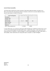
... DRV : Device selection bit 76543210 E7h XX XX - 6.3.2.5.8 Flush Cache [E7h] The Flush Cache command is to write the cache data on the disk is 30 seconds. BSY is set to one.
... DRV : Device selection bit 76543210 E7h XX XX - 6.3.2.5.8 Flush Cache [E7h] The Flush Cache command is to write the cache data on the disk is 30 seconds. BSY is set to one.
Specifications
Page 52
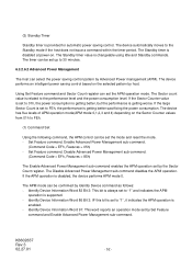
... can be set up to FEh, the performance is set by host. Identify Device Information Word 91: This word reports an operation mode set to 30 minutes. 6.3.2.6.2 Advanced Power Management The host can be confirmed by Identify Device command as follows: - The Standby timer value is provided for automatic power saving...
... can be set up to FEh, the performance is set by host. Identify Device Information Word 91: This word reports an operation mode set to 30 minutes. 6.3.2.6.2 Advanced Power Management The host can be confirmed by Identify Device command as follows: - The Standby timer value is provided for automatic power saving...
Specifications
Page 54
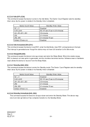
Sector Count Value SC = 0 0 By the power on default, the Standby timer is disabled. 6.3.2.6.4 Idle [97h, E3h] This command causes the device to enter to the Idle Mode. The Sector Count Register sets the standby timer value.
Sector Count Value SC = 0 0 By the power on default, the Standby timer is disabled. 6.3.2.6.4 Idle [97h, E3h] This command causes the device to enter to the Idle Mode. The Sector Count Register sets the standby timer value.
Specifications
Page 76
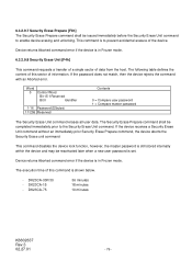
...not match, then the device rejects the command with an Aborted error. Device returns Aborted command error if the device is set. DK23CA-75 36 minutes 18 minutes 10 minutes K6602637 Rev.3 02.27.01 - 76 - The following table defines the content of data from the host. The execution time... Unit command erases all user data. The Security Erase Prepare command shall be completed immediately prior to enable device erasing and unlocking. DK23CA-15 - This command is in Frozen mode. Device returns Aborted command error if the device is to prevent accidental erasure of information...
...not match, then the device rejects the command with an Aborted error. Device returns Aborted command error if the device is set. DK23CA-75 36 minutes 18 minutes 10 minutes K6602637 Rev.3 02.27.01 - 76 - The following table defines the content of data from the host. The execution time... Unit command erases all user data. The Security Erase Prepare command shall be completed immediately prior to enable device erasing and unlocking. DK23CA-15 - This command is in Frozen mode. Device returns Aborted command error if the device is to prevent accidental erasure of information...
Specifications
Page 84
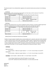
... maximum LBA in LBA mode, the Number of logical cylinder of Identify device command data word 1 is (maximum LBA)/(16 x 63) for DK23CA-30F/30/15, (maximum LBA)/(15 x 63) for DK23CA-75. CHS Mode Maximum sector number and maximum head number are fixed values, and the values are 16 and 63 for... DK23CA-30F/30/15, 15 and 63 for DK23CA-75. Task File Registers 76543210 Cylinder High Maximum LBA Bit23 -16 Cylinder Low Maximum LBA Bit15 - 8 Device/Head - 1 - LBA Mode Maximum LBA issued by...
... maximum LBA in LBA mode, the Number of logical cylinder of Identify device command data word 1 is (maximum LBA)/(16 x 63) for DK23CA-30F/30/15, (maximum LBA)/(15 x 63) for DK23CA-75. CHS Mode Maximum sector number and maximum head number are fixed values, and the values are 16 and 63 for... DK23CA-30F/30/15, 15 and 63 for DK23CA-75. Task File Registers 76543210 Cylinder High Maximum LBA Bit23 -16 Cylinder Low Maximum LBA Bit15 - 8 Device/Head - 1 - LBA Mode Maximum LBA issued by...

Specifications
Page 88
...(16 bit) or DD0-7(8 bit) SYMBOL Description MIN(ns) t0 Cycle Time 120 t1 Address Valid to Address Valid Hold 10 MAX(ns) 30 40 30 K6602637 Rev.3 02.27.01 - 88 - Data Hold 10 t5 DIOR- to DIOR-/DIOW- Recovery 25 t3 DIOW- Negation (MAX) t9 DIOR-/DIOW- Data Setup 20 t4 DIOW...
...(16 bit) or DD0-7(8 bit) SYMBOL Description MIN(ns) t0 Cycle Time 120 t1 Address Valid to Address Valid Hold 10 MAX(ns) 30 40 30 K6602637 Rev.3 02.27.01 - 88 - Data Hold 10 t5 DIOR- to DIOR-/DIOW- Recovery 25 t3 DIOW- Negation (MAX) t9 DIOR-/DIOW- Data Setup 20 t4 DIOW...
Specifications
Page 101
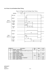
...) tR0 tP0 BSY bit DRDY DRV 1 (device 1) PDIAG- (out) DASP(out) tQ tN1 tR1 tS SYMBOL Description MIN tM RESET- MAX 400 1 450 31s 400 1 30 Units ms ns ms ms ms ms sec K6602637 Rev.3 02.27.01 - 101 - tN1 DRV 1 negate PDIAG- if asserted tQ DRV 1 assert PDIAG- 6.4.3 Power...
...) tR0 tP0 BSY bit DRDY DRV 1 (device 1) PDIAG- (out) DASP(out) tQ tN1 tR1 tS SYMBOL Description MIN tM RESET- MAX 400 1 450 31s 400 1 30 Units ms ns ms ms ms ms sec K6602637 Rev.3 02.27.01 - 101 - tN1 DRV 1 negate PDIAG- if asserted tQ DRV 1 assert PDIAG- 6.4.3 Power...