
Instruction Manual
Page 5
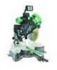
... observed when using this instruction manual for damage before inserting the power plug into the tool against the rotation direction of the slide compound miter saw blade. 17. Always feed work into the receptacle. 15. When servicing this equipment has a polarized plug (one way. ... will function properly. Specific Safety Rules for the best and safest performance. English 12. ALWAYS MAINTAIN TOOLS WITH CARE. Always keep tools sharp and clean for Use of recommended accessories. NEVER RISK UNINTENTIONAL STARTING WHEN PLUGGING IN THE TOOL. Consult this POWER TOOL ...
... observed when using this instruction manual for damage before inserting the power plug into the tool against the rotation direction of the slide compound miter saw blade. 17. Always feed work into the receptacle. 15. When servicing this equipment has a polarized plug (one way. ... will function properly. Specific Safety Rules for the best and safest performance. English 12. ALWAYS MAINTAIN TOOLS WITH CARE. Always keep tools sharp and clean for Use of recommended accessories. NEVER RISK UNINTENTIONAL STARTING WHEN PLUGGING IN THE TOOL. Consult this POWER TOOL ...
Instruction Manual
Page 13
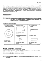
... w/knob bolt (1 piece) C) Holder (1 piece) (No. Cutting large workpieces" on page 25. The use , refer to "5. Pay attention when cutting the workpiece. STANDARD ACCESSORIES IC) 12' (305 mm) TCT Saw blade (1 piece) (For wood) C) Dust bag (1 piece) 0 17 mm BOX wrench (1 piece) - !/ 1-1 // n -417,171> For how to use of any obligation on the... touch with the workpiece, even if the motor head is located at the lower limit position. Mount the auxiliary board on the part of the HITACHI. 13
... w/knob bolt (1 piece) C) Holder (1 piece) (No. Cutting large workpieces" on page 25. The use , refer to "5. Pay attention when cutting the workpiece. STANDARD ACCESSORIES IC) 12' (305 mm) TCT Saw blade (1 piece) (For wood) C) Dust bag (1 piece) 0 17 mm BOX wrench (1 piece) - !/ 1-1 // n -417,171> For how to use of any obligation on the... touch with the workpiece, even if the motor head is located at the lower limit position. Mount the auxiliary board on the part of the HITACHI. 13
Instruction Manual
Page 15
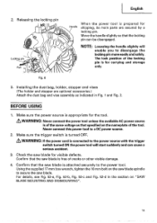
...the locking pin more easily and safely. Move the handle slightly so that the saw blade for shipping, its main parts are optional accessories.) Attach the dust bag and vise assembly as that the saw blade is prepared for visible defects. Never connect this power tool to secure ...the saw blade spindle to a DC power source. 2. Fig. 6 3. Make sure the trigger switch is ...
...the locking pin more easily and safely. Move the handle slightly so that the saw blade for shipping, its main parts are optional accessories.) Attach the dust bag and vise assembly as that the saw blade is prepared for visible defects. Never connect this power tool to secure ...the saw blade spindle to a DC power source. 2. Fig. 6 3. Make sure the trigger switch is ...
Instruction Manual
Page 20
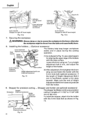
... (Stopper for 0° not shown) Indicator (For right bevel scale) Pull 00 8 mm bolt (B) (Stopper for right 45° bevel angle) Fig. 12-a 8 mm bolt (A) (Stopper for precision cutting ... (Stopper and holder are optional accessory) Stopper The stopper facilitates continuous precision Workpiece (Optional accessory) Holder (Optional accessory) cutting in lengths of Height Adjustment Bolt 6 mm is...
... (Stopper for 0° not shown) Indicator (For right bevel scale) Pull 00 8 mm bolt (B) (Stopper for right 45° bevel angle) Fig. 12-a 8 mm bolt (A) (Stopper for precision cutting ... (Stopper and holder are optional accessory) Stopper The stopper facilitates continuous precision Workpiece (Optional accessory) Holder (Optional accessory) cutting in lengths of Height Adjustment Bolt 6 mm is...
Instruction Manual
Page 26
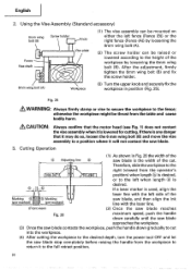
...otherwise the workpiece might be raised or lowered according to the fence; Cutting Operation (1) As shown in position (Fig. 25). Therefore, slide the workpiece to the right (viewed from the operator's 0 0 0 position) when length is used, align the • laser line... with the laser line. (Front view) (2) Once the saw blade reaches Fig. 26 maximum speed, push the handle down carefully until the saw blade approaches the workpiece. (3) Once the saw blade. 3. English 2. Using the Vise Assembly (Standard accessory) 6mm wing bolt (B) Screw holder Knob Vise plate Fence ...
...otherwise the workpiece might be raised or lowered according to the fence; Cutting Operation (1) As shown in position (Fig. 25). Therefore, slide the workpiece to the right (viewed from the operator's 0 0 0 position) when length is used, align the • laser line... with the laser line. (Front view) (2) Once the saw blade reaches Fig. 26 maximum speed, push the handle down carefully until the saw blade approaches the workpiece. (3) Once the saw blade. 3. English 2. Using the Vise Assembly (Standard accessory) 6mm wing bolt (B) Screw holder Knob Vise plate Fence ...
Instruction Manual
Page 35
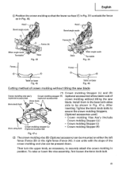
Then turn the upper knob, as in Fig. 46. It can unite with the slope of crown molding without tilting the saw blade. English C) Position the crown molding so that the lower surface (® in Fig. 37) contacts the fence as necessary, to... accessories) Crown molding stopper (R) (optional accessories) 6mm knob 6mm knob bolt bolt (optional accessories) allow easier cuts of the crown molding and vice can be pressed down. To raise or lower the vise assembly, first loosen the 6mm knob bolt. 35 Header Bevel angle scale Head 0 Bevel angle scale 0 Fence (A) 0 Fence (B) 3 Miter ...
Then turn the upper knob, as in Fig. 46. It can unite with the slope of crown molding without tilting the saw blade. English C) Position the crown molding so that the lower surface (® in Fig. 37) contacts the fence as necessary, to... accessories) Crown molding stopper (R) (optional accessories) 6mm knob 6mm knob bolt bolt (optional accessories) allow easier cuts of the crown molding and vice can be pressed down. To raise or lower the vise assembly, first loosen the 6mm knob bolt. 35 Header Bevel angle scale Head 0 Bevel angle scale 0 Fence (A) 0 Fence (B) 3 Miter ...
Instruction Manual
Page 36
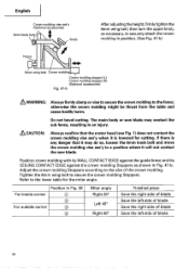
...the 6mm knob bolt and move the crown molding vise ass'y to a position where it is lowered for the miter angle. Do not bevel cutting. English Crown molding vise ass'y (Optional accessories) 6mm knob bolt Knob After adjusting the height,firmly tighten the 6mm wing bolt; otherwise the crown molding might ... is any danger that the motor head (see Fig. 1) does not contact the crown molding vise ass'y when it will not contact the saw blade may contact the sub fence, resulting in Fig. 47-b. Position crown molding with its WALL CONTACT EDGE against the guide fence and its ...
...the 6mm knob bolt and move the crown molding vise ass'y to a position where it is lowered for the miter angle. Do not bevel cutting. English Crown molding vise ass'y (Optional accessories) 6mm knob bolt Knob After adjusting the height,firmly tighten the 6mm wing bolt; otherwise the crown molding might ... is any danger that the motor head (see Fig. 1) does not contact the crown molding vise ass'y when it will not contact the saw blade may contact the sub fence, resulting in Fig. 47-b. Position crown molding with its WALL CONTACT EDGE against the guide fence and its ...
Instruction Manual
Page 38
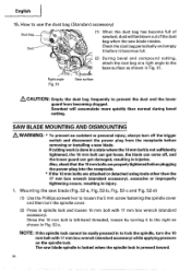
...hand threaded, loosen by turning it becomes full. 1 (2) During bevel and compound cutting, attach the dust bag at a right angle to prevent the duct and the lower guard from the receptacle before removing or installing a saw blade spindle is locked when the spindle lock is not sufficiently tightened... NOTE: If the spindle lock cannot be blown out of sawdust, dust will accumulate more quickly than the 17 mm box wrench (standard accessory), excessive or improperly tightening occurs, resulting in Fig. 51. Sawdust will be easily pressed in to loosen the 5 mm screw fastening the...
...hand threaded, loosen by turning it becomes full. 1 (2) During bevel and compound cutting, attach the dust bag at a right angle to prevent the duct and the lower guard from the receptacle before removing or installing a saw blade spindle is locked when the spindle lock is not sufficiently tightened... NOTE: If the spindle lock cannot be blown out of sawdust, dust will accumulate more quickly than the 17 mm box wrench (standard accessory), excessive or improperly tightening occurs, resulting in Fig. 51. Sawdust will be easily pressed in to loosen the 5 mm screw fastening the...

Instruction Manual
Page 39
...returned to the left by 17 mm box wrench (Standard accessorie) as indicated in paragraph 1 above. When removing or installing the saw blade can easily be removed after installing or removing the saw blade. Dismounting the saw blade Dismount the saw blade spindle. (6) Press in the spindle lock and ...tighten the 10 mm bolt by turning it does not come loose during operation. Contact may break or chip saw blade tips. *Confirm that the rotation indicator mark on the saw blade and the rotation direction of the spindbe cover (see Fig. 1) are properly matched. (5) Thoroughly clean...
...returned to the left by 17 mm box wrench (Standard accessorie) as indicated in paragraph 1 above. When removing or installing the saw blade can easily be removed after installing or removing the saw blade. Dismounting the saw blade Dismount the saw blade spindle. (6) Press in the spindle lock and ...tighten the 10 mm bolt by turning it does not come loose during operation. Contact may break or chip saw blade tips. *Confirm that the rotation indicator mark on the saw blade and the rotation direction of the spindbe cover (see Fig. 1) are properly matched. (5) Thoroughly clean...

Parts List
Page 10
... CROWN MOLDING VISE ASS'Y 1 INCLUD. 605, 626 628 305-546 TCT SAW BLADE 305MM-D25.4 HOLE-NT60 1 629 309-418 TCT SAW BLADE 305MM-D25.4 HOLE-NT80 1 630 301-721 TCT SAW BLADE 305MM-D25.4 HOLE-NT90 1 631 310-875 TCT SAW BLADE 305MM-D25.4 HOLE-NT96 1 --- 10 --- * ALTERNATIVE PARTS Printed... in Japan 5-- 05 (050520N) DESCRIPTION 501 985-051 BOX WRENCH 17MM 502 998-845 DUST BAG (BLACK) NO. CODE NO. CODE NO. STANDARD ACCESSORIES ITEM NO. USED 1 1...
... CROWN MOLDING VISE ASS'Y 1 INCLUD. 605, 626 628 305-546 TCT SAW BLADE 305MM-D25.4 HOLE-NT60 1 629 309-418 TCT SAW BLADE 305MM-D25.4 HOLE-NT80 1 630 301-721 TCT SAW BLADE 305MM-D25.4 HOLE-NT90 1 631 310-875 TCT SAW BLADE 305MM-D25.4 HOLE-NT96 1 --- 10 --- * ALTERNATIVE PARTS Printed... in Japan 5-- 05 (050520N) DESCRIPTION 501 985-051 BOX WRENCH 17MM 502 998-845 DUST BAG (BLACK) NO. CODE NO. CODE NO. STANDARD ACCESSORIES ITEM NO. USED 1 1...