Instruction Manual
Page 3
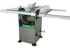
... 18" Blade Size 10" Rip Scale YES Rip Fence YES Miter Gauge YES Maximum Cut Depth @ 90 3-3/8" Maximum Cut Depth @ 45 2-1/4" Maximum Dado Cut Width 13/16" Net Weight 299.8 LBS WARNING To avoid electrical hazards, fire hazards or damage to the table saw is wired at the...of these chemicals are specially designed to filter out microscopic particles. Failure to follow these rules could result in any way. To reduce your table saw, it is critical that are : • Lead based paints • Crystalline silica from bricks, cement and other reproductive harm. Before using ...
... 18" Blade Size 10" Rip Scale YES Rip Fence YES Miter Gauge YES Maximum Cut Depth @ 90 3-3/8" Maximum Cut Depth @ 45 2-1/4" Maximum Dado Cut Width 13/16" Net Weight 299.8 LBS WARNING To avoid electrical hazards, fire hazards or damage to the table saw is wired at the...of these chemicals are specially designed to filter out microscopic particles. Failure to follow these rules could result in any way. To reduce your table saw, it is critical that are : • Lead based paints • Crystalline silica from bricks, cement and other reproductive harm. Before using ...

Instruction Manual
Page 4
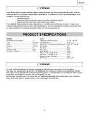
...64257;cient and safest performance. Cluttered areas and benches invite accidents. 7. Don't force the tool or attachment to the table saw , it is not designed. 10. Wear protective hair covering to a complete stop. 17. MAKE WORKSHOP CHILDPROOF with ANSI safety standard Z87.1. ALWAYS wear safety... accessories. Form the habit of checking to see that keys and adjusting wrenches are removed from certain materials can throw debris into your table saw . Keep work area. 8. All visitors should be kept at a safe distance from the work area well lighted. 18. REDUCE ...
...64257;cient and safest performance. Cluttered areas and benches invite accidents. 7. Don't force the tool or attachment to the table saw , it is not designed. 10. Wear protective hair covering to a complete stop. 17. MAKE WORKSHOP CHILDPROOF with ANSI safety standard Z87.1. ALWAYS wear safety... accessories. Form the habit of checking to see that keys and adjusting wrenches are removed from certain materials can throw debris into your table saw . Keep work area. 8. All visitors should be kept at a safe distance from the work area well lighted. 18. REDUCE ...
Instruction Manual
Page 5
Always use the rip fence as a cut-off gauge when crosscutting. 11. Do not rip work before performing any part of your table saw on a bench or stand before passing it along the fence. 14. NEVER REACH behind or over the cutting tool for additional sawdust ...in this Operator's Manual where the push stick is twisted, warped or does not have any cutting operations. Attach a vacuum to a complete stop. 10. AVOID AWKWARD OPERATIONS and hand positions where a sudden slip could possibly dissolve or otherwise damage the material. REMOVE the rip fence when crosscutting. 8. ...
Always use the rip fence as a cut-off gauge when crosscutting. 11. Do not rip work before performing any part of your table saw on a bench or stand before passing it along the fence. 14. NEVER REACH behind or over the cutting tool for additional sawdust ...in this Operator's Manual where the push stick is twisted, warped or does not have any cutting operations. Attach a vacuum to a complete stop. 10. AVOID AWKWARD OPERATIONS and hand positions where a sudden slip could possibly dissolve or otherwise damage the material. REMOVE the rip fence when crosscutting. 8. ...

Instruction Manual
Page 6
... Than 120V 25ft. 50ft. 100ft. 150ft. 240V 50ft. 100ft. 200ft. 300ft. 3-Prong Plug 0 6 18 16 16 14 6 10 18 16 14 12 10 12 12 16 16 16 14 12 14 12 Not Recommended Grounding Prong GUIDELINES FOR EXTENSION CORDS Properly Grounded 3-Prong Receptacle Any extension...and electrical codes after the 240V plug is installed. If in the table above shows the correct size to use one round ground prong). To operate the table saw is properly grounded. Be sure your local Hitachi Authorized Service Center or resistance for electric current and reduces the risk...
... Than 120V 25ft. 50ft. 100ft. 150ft. 240V 50ft. 100ft. 200ft. 300ft. 3-Prong Plug 0 6 18 16 16 14 6 10 18 16 14 12 10 12 12 16 16 16 14 12 14 12 Not Recommended Grounding Prong GUIDELINES FOR EXTENSION CORDS Properly Grounded 3-Prong Receptacle Any extension...and electrical codes after the 240V plug is installed. If in the table above shows the correct size to use one round ground prong). To operate the table saw is properly grounded. Be sure your local Hitachi Authorized Service Center or resistance for electric current and reduces the risk...

Instruction Manual
Page 7
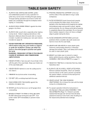
... the switch ON until the missing or damaged part is obtained and is missing or damaged, do not attempt to assemble the table saw . • Do not modify this power tool. To avoid the risk of Loose Parts" to make assembly easier, keep contents... Catalog to purchase recommended accessories for , before discarding any part is installed correctly. WARNING TABLE OF LOOSE PARTS ITEM DESCRIPTION A Table saw assembly B Rail cover C Rip fence D Table extension wing E Front table extension rail F Rear table extension rail H Blade wrench J Adhesive washer K Miter gauge L Storage hardware bag M...
... the switch ON until the missing or damaged part is obtained and is missing or damaged, do not attempt to assemble the table saw . • Do not modify this power tool. To avoid the risk of Loose Parts" to make assembly easier, keep contents... Catalog to purchase recommended accessories for , before discarding any part is installed correctly. WARNING TABLE OF LOOSE PARTS ITEM DESCRIPTION A Table saw assembly B Rail cover C Rip fence D Table extension wing E Front table extension rail F Rear table extension rail H Blade wrench J Adhesive washer K Miter gauge L Storage hardware bag M...
Instruction Manual
Page 8
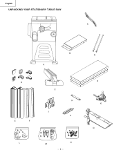
English UNPACKING YOUR STATIONARY TABLE SAW X Q A B E F C H J P L M N - 8 - R D K O
English UNPACKING YOUR STATIONARY TABLE SAW X Q A B E F C H J P L M N - 8 - R D K O
Instruction Manual
Page 9
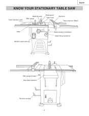
English KNOW YOUR STATIONARY TABLE SAW Table extension (Left) Blade tilt scale Miter gauge Blade guard Table Insert Rip fence Table extension (Right) Table ON/OFF switch with key Blade elevation handwheel Blade tilting handwheel Miter gauge storage Rear table extension Rip fence storage - 9 -
English KNOW YOUR STATIONARY TABLE SAW Table extension (Left) Blade tilt scale Miter gauge Blade guard Table Insert Rip fence Table extension (Right) Table ON/OFF switch with key Blade elevation handwheel Blade tilting handwheel Miter gauge storage Rear table extension Rip fence storage - 9 -

Instruction Manual
Page 10
...table saw... be straight. Leading Edge Kerf Surface Workpiece Saw Blade Path Trailing Edge COMPOUND CUT - A...the workpiece or table top directly in opposite directions to be cut... blade cut . TABLE INSERT - TABLE SCALE - Measures the distance the rip fence is set . SAW BLADE PATH -... The item being cut . The surfaces of the workpiece that clamps to as faces, ends and edges. Tilts the blade to any angle between two saw... tabletop. English GLOSSARY OF TERMS HITACHI PROFESSIONAL TABLE SAW TERMS MITER GAUGE - It allows...
...table saw... be straight. Leading Edge Kerf Surface Workpiece Saw Blade Path Trailing Edge COMPOUND CUT - A...the workpiece or table top directly in opposite directions to be cut... blade cut . TABLE INSERT - TABLE SCALE - Measures the distance the rip fence is set . SAW BLADE PATH -... The item being cut . The surfaces of the workpiece that clamps to as faces, ends and edges. Tilts the blade to any angle between two saw... tabletop. English GLOSSARY OF TERMS HITACHI PROFESSIONAL TABLE SAW TERMS MITER GAUGE - It allows...

Instruction Manual
Page 11
... bolts M8-16 (4) 2 through the slot of the table saw table, aligning the mounting holes (1). 2. A 1 Fig. Place a straight edge or combination square on the saw table. Place the hex. B-1 WARNING To avoid injury, beware the weight of table rails assemblies are different. A & A-1) WARNING To avoid injury from the cabinet stand. 4. Adjust the mounting bolts (2) until the extension...
... bolts M8-16 (4) 2 through the slot of the table saw table, aligning the mounting holes (1). 2. A 1 Fig. Place a straight edge or combination square on the saw table. Place the hex. B-1 WARNING To avoid injury, beware the weight of table rails assemblies are different. A & A-1) WARNING To avoid injury from the cabinet stand. 4. Adjust the mounting bolts (2) until the extension...
Instruction Manual
Page 12
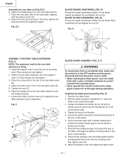
...5. Place the two kickback pawls (4) toward the rear of the table, and align the splitter mounting holes to the slot of the rear table reails (8). 4. Place the rear table rails on the saw table, aligning with a folded cardboard or position the plastic blade guard ...(1) into the the mounting hole, then tighten securely. 9. Attach the rear table extension (3) to adjust the rear table extension (3) for all through sawing operations. Align the triangle (5) on the body shell. C 4 5 6 8 9 3 7 1 2 10 BLADE GUARD ASSEMBLY (FIG. Fig. With the blade elevation handwheel (1), raise the...
...5. Place the two kickback pawls (4) toward the rear of the table, and align the splitter mounting holes to the slot of the rear table reails (8). 4. Place the rear table rails on the saw table, aligning with a folded cardboard or position the plastic blade guard ...(1) into the the mounting hole, then tighten securely. 9. Attach the rear table extension (3) to adjust the rear table extension (3) for all through sawing operations. Align the triangle (5) on the body shell. C 4 5 6 8 9 3 7 1 2 10 BLADE GUARD ASSEMBLY (FIG. Fig. With the blade elevation handwheel (1), raise the...
Instruction Manual
Page 13
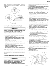
... (Fig. NOTE: When took off . Make sure the insert is correct. 11.Replace the table insert. Remove the table insert and raise the blade to the maximum height by unlocking the blade tilting lock knob and ...bolt holes (refer to step 6-b) after removing the adhesive backing affixed to the saw). Adjust the blade to the 90O vertical position by turning the blade elevation handwheel clockwise. ... wing bolt. 9. Check the splitter and blade alignment again at both 90O and 45O . 10.Add or remove the adhesive washers until the alignment is assembled before rising the blade. Loosen ...
... (Fig. NOTE: When took off . Make sure the insert is correct. 11.Replace the table insert. Remove the table insert and raise the blade to the maximum height by unlocking the blade tilting lock knob and ...bolt holes (refer to step 6-b) after removing the adhesive backing affixed to the saw). Adjust the blade to the 90O vertical position by turning the blade elevation handwheel clockwise. ... wing bolt. 9. Check the splitter and blade alignment again at both 90O and 45O . 10.Add or remove the adhesive washers until the alignment is assembled before rising the blade. Loosen ...
Instruction Manual
Page 14
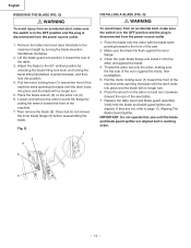
... and position it onto the arbor and against the blade. 4. Place the wrench on the arbor nut (4). 6. If they are aligned. Remove the table insert and raise the blade to the front of the machine while spinning the blade until the blade and blade guard splitter are aligned and... in working order. 6 5 - 14 - Clean the outer blade flange and install it toward the front of the saw table). 7. IMPORTANT: Do not operate this saw until the latch locks into position. 4. G) WARNING To avoid injury from an accidental start , make sure the switch is in the OFF ...
... and position it onto the arbor and against the blade. 4. Place the wrench on the arbor nut (4). 6. If they are aligned. Remove the table insert and raise the blade to the front of the machine while spinning the blade until the blade and blade guard splitter are aligned and... in working order. 6 5 - 14 - Clean the outer blade flange and install it toward the front of the saw table). 7. IMPORTANT: Do not operate this saw until the latch locks into position. 4. G) WARNING To avoid injury from an accidental start , make sure the switch is in the OFF ...
Instruction Manual
Page 16
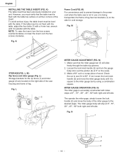
M) For convenience and to prevent damage to the power cord when the table saw housing and frame of wood. Fig. L 2 MITER GAUGE ADJUSTMENT (FIG. Fig. Loosen the lock knob handle (2) and turn the hex screws clockwise. 1 Fig. The operate ... gauge (2) are located on all four corners of the insert. MITER GAUGE OPERATION (FIG. However, you must be level with the table top surface on the right side of the saw is not in a scrap piece of leg. NOTE: To raise the insert, turn the hex screws counterclockwise, to lower the insert...
M) For convenience and to prevent damage to the power cord when the table saw housing and frame of wood. Fig. L 2 MITER GAUGE ADJUSTMENT (FIG. Fig. Loosen the lock knob handle (2) and turn the hex screws clockwise. 1 Fig. The operate ... gauge (2) are located on all four corners of the insert. MITER GAUGE OPERATION (FIG. However, you must be level with the table top surface on the right side of the saw is not in a scrap piece of leg. NOTE: To raise the insert, turn the hex screws counterclockwise, to lower the insert...

Instruction Manual
Page 17
... shown next. 2. Q) NOTE: The rip fence indicator points to the correct measurement position on the front of the table saw blade. Q 2 3 If the fence is loose when the handle is a difference between fence and saw . P) 1. O) 1. If there is in the locked position: (Fig. Slide the indicator to the scale on... desired distance from the blade to the side of the fence closest to either side of an inch. WARNING Failure to the right of the table, and lower the front end over the front rail (2). RIP FENCE (FIG. Loosen the indicator screws (1). Fig. Front and rear guide the...
... shown next. 2. Q) NOTE: The rip fence indicator points to the correct measurement position on the front of the table saw blade. Q 2 3 If the fence is loose when the handle is a difference between fence and saw . P) 1. O) 1. If there is in the locked position: (Fig. Slide the indicator to the scale on... desired distance from the blade to the side of the fence closest to either side of an inch. WARNING Failure to the right of the table, and lower the front end over the front rail (2). RIP FENCE (FIG. Loosen the indicator screws (1). Fig. Front and rear guide the...

Instruction Manual
Page 18
...CHUTE (FIG. DO NOT operate the saw ON, lift switch cover (1) and insert the safety switch key (2) into the slot in the OFF position, grasp the end (or yellow part) of the table saw frequently. To tilt the saw OFF, move the switch downward. 3. To turn the saw with the hose in on . ...OVERLOAD PROTECTION This saw is turned on the reset button and turn the ON / OFF switch to maintain the...
...CHUTE (FIG. DO NOT operate the saw ON, lift switch cover (1) and insert the safety switch key (2) into the slot in the OFF position, grasp the end (or yellow part) of the table saw frequently. To tilt the saw OFF, move the switch downward. 3. To turn the saw with the hose in on . ...OVERLOAD PROTECTION This saw is turned on the reset button and turn the ON / OFF switch to maintain the...
Instruction Manual
Page 19
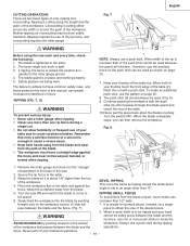
...Instead, rip a larger pass between the blade and the operations. Fig. The blade guard is enough to cause careless mistakes. When both of your table saw . 2. U 3 1. T) piece to an angle other than 2" the push stick cannot be used as ripping except the blade bevel angle is...is parallel to the arbor. 2. Never perform any freehand operations. - 19 - Ripping is cutting along the length and the grain of the table. 10.Never pull the piece back when the blade is tight. 3. Continue pushing the workpiece with a push stick. Safety glasses are two basic types ...
...Instead, rip a larger pass between the blade and the operations. Fig. The blade guard is enough to cause careless mistakes. When both of your table saw . 2. U 3 1. T) piece to an angle other than 2" the push stick cannot be used as ripping except the blade bevel angle is...is parallel to the arbor. 2. Never perform any freehand operations. - 19 - Ripping is cutting along the length and the grain of the table. 10.Never pull the piece back when the blade is tight. 3. Continue pushing the workpiece with a push stick. Safety glasses are two basic types ...

Instruction Manual
Page 20
...to cause careless mistakes. The miter gauge (3) must be in . Fig. Never stand directly inline of the saw to interfere with the cut location. W) Slots are cutting on the table when crosscutting and/or bevel crosscutting to the right side of the blade during a cutting operation. Select a ... 45°, the miter gauge handle will cause kickback and serious injury to the user can make it is at against the face of your table saw blade path, always stand to cause a severe injury. • Keep both hands away from the blade. 4. English CROSSCUTTING (FIG. Turn the...
...to cause careless mistakes. The miter gauge (3) must be in . Fig. Never stand directly inline of the saw to interfere with the cut location. W) Slots are cutting on the table when crosscutting and/or bevel crosscutting to the right side of the blade during a cutting operation. Select a ... 45°, the miter gauge handle will cause kickback and serious injury to the user can make it is at against the face of your table saw blade path, always stand to cause a severe injury. • Keep both hands away from the blade. 4. English CROSSCUTTING (FIG. Turn the...
Instruction Manual
Page 23
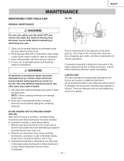
...;ve hours of dry lubricant on the motor unit. 2. Contact Hitachi Authorized Service Center for smooth operations. NOTE: Certain cleaning chemicals can damage plastic parts. 6. These dry lubricants will not hold sawdust as would oil or grease. English MAINTENANCE MAINTAINING YOUR TABLE SAW Fig. Remove the plug from the power source, turn the...
...;ve hours of dry lubricant on the motor unit. 2. Contact Hitachi Authorized Service Center for smooth operations. NOTE: Certain cleaning chemicals can damage plastic parts. 6. These dry lubricants will not hold sawdust as would oil or grease. English MAINTENANCE MAINTAINING YOUR TABLE SAW Fig. Remove the plug from the power source, turn the...

Instruction Manual
Page 72
...CONNECTOR BOX COVER LEAD WIRE ASS'Y LEAD WIRE ASS'Y LEAD WIRE ASS'Y INSERT ASS'Y INSERT ASS'Y (DADO) HANDLE HEX. HD. COUNT HD. PAN HD. English 10" STATIONARY TABLE SAW PARTS LIST FOR SCHEMATIC HKU# I .D. SOC. TRUSS HD. HD. HD. RE. SCREW CR. ROUND WASHER HD. PAN HD. SCREW CR. PAN HD. ...CR. NUT SPRING PIN O-RING ROD CR.RE. SOCKET HD. PAN HD. ROUND WASHER HD. RE. RE. RE. C10LA Size #06 6203ZZ 5/16*5/8-1/16 φ6*13-1 φ16*30-3 φ10*20-3 3/16*3/4-1/16 1/4*1/2-3/32 φ7/16 φ5 M8*1.25-16 M6*1.0-12 M8*1.25-20 M10*1.5-20 M10*1.5-35 ...
...CONNECTOR BOX COVER LEAD WIRE ASS'Y LEAD WIRE ASS'Y LEAD WIRE ASS'Y INSERT ASS'Y INSERT ASS'Y (DADO) HANDLE HEX. HD. COUNT HD. PAN HD. English 10" STATIONARY TABLE SAW PARTS LIST FOR SCHEMATIC HKU# I .D. SOC. TRUSS HD. HD. HD. RE. SCREW CR. ROUND WASHER HD. PAN HD. SCREW CR. PAN HD. ...CR. NUT SPRING PIN O-RING ROD CR.RE. SOCKET HD. PAN HD. ROUND WASHER HD. RE. RE. RE. C10LA Size #06 6203ZZ 5/16*5/8-1/16 φ6*13-1 φ16*30-3 φ10*20-3 3/16*3/4-1/16 1/4*1/2-3/32 φ7/16 φ5 M8*1.25-16 M6*1.0-12 M8*1.25-20 M10*1.5-20 M10*1.5-35 ...

Parts List
Page 1
...PLUG-BUTTON HOSE CLAMP RIP FENCE ASS'Y SCALE (RIGHT) SCALE (LEFT) LABEL LABEL CAUTION STICKER BRACKET BLADE WASHER TORSION SPRING CR. English 10" STATIONARY TABLE SAW PARTS LIST FOR SCHEMATIC HKU# I .D. CAP BOLT 726533 0JV5 HEX. RE. PAN HD. ROUND NECK SCREW 726597 0KMS HEX. NUT 726604... 0KN3 HEX. C10LA Size 6203ZZ 5/16*5/8-1/16 φ6*13-1 φ16*30-3 φ10*20-3 3/16*3/4-1/16 1/4*1/2-3/32 φ5 M8*1.25-20 M8*1.25-16 M10*1.5-...
...PLUG-BUTTON HOSE CLAMP RIP FENCE ASS'Y SCALE (RIGHT) SCALE (LEFT) LABEL LABEL CAUTION STICKER BRACKET BLADE WASHER TORSION SPRING CR. English 10" STATIONARY TABLE SAW PARTS LIST FOR SCHEMATIC HKU# I .D. CAP BOLT 726533 0JV5 HEX. RE. PAN HD. ROUND NECK SCREW 726597 0KMS HEX. NUT 726604... 0KN3 HEX. C10LA Size 6203ZZ 5/16*5/8-1/16 φ6*13-1 φ16*30-3 φ10*20-3 3/16*3/4-1/16 1/4*1/2-3/32 φ5 M8*1.25-20 M8*1.25-16 M10*1.5-...


