

Specifications
Page 5
Formatted capacity by model number. 16 Table 2. Operating mode 21 Table 11. Power consumption efficiency 28 Table 16. Mounting hole locations 32 Figure 3. Interface connector pin assignments 39 Figure 4. Parameter descriptions 41 Figure 5 Initial Setting 58 Figure 6 Usual Operation 59 Figure 7 Password Lost 60 Figure 8 Set Max security mode transition 65 Figure 9 Seek overlap 65 Figure 10 Selective self-test test span example 145 List of 176 Performance characteristics 18 Table 5. Environmental condition 25 Table...
Formatted capacity by model number. 16 Table 2. Operating mode 21 Table 11. Power consumption efficiency 28 Table 16. Mounting hole locations 32 Figure 3. Interface connector pin assignments 39 Figure 4. Parameter descriptions 41 Figure 5 Initial Setting 58 Figure 6 Usual Operation 59 Figure 7 Password Lost 60 Figure 8 Set Max security mode transition 65 Figure 9 Seek overlap 65 Figure 10 Selective self-test test span example 145 List of 176 Performance characteristics 18 Table 5. Environmental condition 25 Table...

Specifications
Page 6
... 49 Table 30 Default Register Values 50 Table 31 Diagnostic Codes 50 Table 32 Reset error register values 50 Table 33 Device's behavior by models for device lock operation - Continued --- 93 Table 60 Identify device information --- Continued --- 98 Table 64 Number of cylinders/heads/sectors by models for HTS7232XXL9SA6X / HTS7232XXL9A36X 99 Table 65 Number of cylinders/heads/sectors by ATA commands 51 Table 34 Power conditions 53 Table 35 Command table for device lock operation 61 Table 36...
... 49 Table 30 Default Register Values 50 Table 31 Diagnostic Codes 50 Table 32 Reset error register values 50 Table 33 Device's behavior by models for device lock operation - Continued --- 93 Table 60 Identify device information --- Continued --- 98 Table 64 Number of cylinders/heads/sectors by models for HTS7232XXL9SA6X / HTS7232XXL9A36X 99 Table 65 Number of cylinders/heads/sectors by ATA commands 51 Table 34 Power conditions 53 Table 35 Command table for device lock operation 61 Table 36...

Specifications
Page 7
... 122 Error data structure Table 123 Self-test log data structure Table 124 Selective self-test log data structure Table 125 S.M.A.R.T. Function Set Command (B0h) Table 112 Log sector addresses Table 113 Device Attribute Data Structure Table 114 Individual Attribute Data Structure Table 115 Status Flag Definitions Table 116 Device Attribute Thresholds Data Structure Table 117 Individual Threshold Data Structure Table 118 SMART Log Directory Table 119 S.M.A.R.T. Error Codes...
... 122 Error data structure Table 123 Self-test log data structure Table 124 Selective self-test log data structure Table 125 S.M.A.R.T. Function Set Command (B0h) Table 112 Log sector addresses Table 113 Device Attribute Data Structure Table 114 Individual Attribute Data Structure Table 115 Status Flag Definitions Table 116 Device Attribute Thresholds Data Structure Table 117 Individual Threshold Data Structure Table 118 SMART Log Directory Table 119 S.M.A.R.T. Error Codes...

Specifications
Page 39
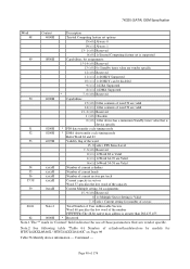
... a device uses 3.3V, then all V33 pins must be terminated. Interface connector pin assignments All pins are :(1)the ground pins P4 and P12;(2) the pre-charge power pins and the other ground pins; Figure 3. and (3) the signal pins and the rest of 176 Otherwise, it is optional to terminate any of the V12 pins. 7K320 SATA OEM Specification 7 Electrical interface specifications 7.1 Cabling The maximum cable length from each voltage. Otherwise...
... a device uses 3.3V, then all V33 pins must be terminated. Interface connector pin assignments All pins are :(1)the ground pins P4 and P12;(2) the pre-charge power pins and the other ground pins; Figure 3. and (3) the signal pins and the rest of 176 Otherwise, it is optional to terminate any of the V12 pins. 7K320 SATA OEM Specification 7 Electrical interface specifications 7.1 Cabling The maximum cable length from each voltage. Otherwise...

Specifications
Page 49
... After power on POR is reset. The device resets the interface circuitry as well as Soft Reset. Soft Reset (Software Reset) SRST bit in the Device Control Register is set by Initialize Device Parameter) - Number of CHS (set , then is shown in "Table 30 Default Register Values" on Page 50. (*3) The Set Features command with Feature register = CCh enables the device to revert these parameters to standby mode. Write cache - In other mechanical parametric, and sets default...
... After power on POR is reset. The device resets the interface circuitry as well as Soft Reset. Soft Reset (Software Reset) SRST bit in the Device Control Register is set by Initialize Device Parameter) - Number of CHS (set , then is shown in "Table 30 Default Register Values" on Page 50. (*3) The Set Features command with Feature register = CCh enables the device to revert these parameters to standby mode. Write cache - In other mechanical parametric, and sets default...

Specifications
Page 52
... DEVICE PARAMETERS command, the host requests the number of sectors per logical track and the number of the data sector on the device's media is always true: LBA = ( (cylinder * heads_per_cylinder + heads) * sectors_per_track ) + sector - 1 where heads_per_cylinder and sectors_per_track are numbered from 1 to the maximum value allowed by a logical sector address. The following register. When the host selects a CHS translation mode using the L bit in requested mode. So a host system must set...
... DEVICE PARAMETERS command, the host requests the number of sectors per logical track and the number of the data sector on the device's media is always true: LBA = ( (cylinder * heads_per_cylinder + heads) * sectors_per_track ) + sector - 1 where heads_per_cylinder and sectors_per_track are numbered from 1 to the maximum value allowed by a logical sector address. The following register. When the host selects a CHS translation mode using the L bit in requested mode. So a host system must set...
Specifications
Page 56
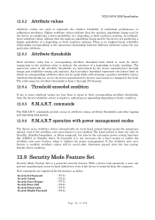
... condition existing. So basically it utilizes the power management. Attribute thresholds are set at the device manufacturer's factory and cannot be equal while still retaining a positive reliability status. commands provide access to attribute values, attribute thresholds and other logging and reporting information. 12.8.6 S.M.A.R.T operation with power management modes The device saves attribute values automatically on every head unload timing except the emergency unload, even...
... condition existing. So basically it utilizes the power management. Attribute thresholds are set at the device manufacturer's factory and cannot be equal while still retaining a positive reliability status. commands provide access to attribute values, attribute thresholds and other logging and reporting information. 12.8.6 S.M.A.R.T operation with power management modes The device saves attribute values automatically on every head unload timing except the emergency unload, even...

Specifications
Page 57
... can set a initial Master Password using the Security Set Password command, without enabling the Device Lock Function. 12.9.5.2 User Password setting When a User Password is set by a security unlock or a security erase unit command. Otherwise, if the User Password is entered by Security Set Password command with the Master Password, but the Master Password can update the device lock function, set , the device enables the Device Lock Function, and then the device is required. Device Locked mode The device disables media access commands after power on . The valid revision codes...
... can set a initial Master Password using the Security Set Password command, without enabling the Device Lock Function. 12.9.5.2 User Password setting When a User Password is set by a security unlock or a security erase unit command. Otherwise, if the User Password is entered by Security Set Password command with the Master Password, but the Master Password can update the device lock function, set , the device enables the Device Lock Function, and then the device is required. Device Locked mode The device disables media access commands after power on . The valid revision codes...
Specifications
Page 68
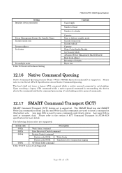
... device parameters Power Management Feature Set Standby Timer Security mode state Set max address Set feature Set multiple mode Table 38 Preserved Software Setting Track length Contents Number of head Number of cylinder Capacity Time to fall into standby mode Security freeze lock Security unlock Capacity Write Cache Enable/Disable Set Transfer Mode Advanced Power Management Enable/Disable Read Look-Ahead Reverting to Defaults Block size 12.16 Native Command Queuing Native Command Queuing feature (Read / Write FPDMA Queued commands) is used to transport data. The SMART Read Log and SMART...
... device parameters Power Management Feature Set Standby Timer Security mode state Set max address Set feature Set multiple mode Table 38 Preserved Software Setting Track length Contents Number of head Number of cylinder Capacity Time to fall into standby mode Security freeze lock Security unlock Capacity Write Cache Enable/Disable Set Transfer Mode Advanced Power Management Enable/Disable Read Look-Ahead Reverting to Defaults Block size 12.16 Native Command Queuing Native Command Queuing feature (Read / Write FPDMA Queued commands) is used to transport data. The SMART Read Log and SMART...

Specifications
Page 70
... Enable Operations S.M.A.R.T. 7K320 (SATA) OEM Specification Security Set Password Security Unlock Set Max Set Password Set Max Unlock S.M.A.R.T Write Log Sector Write Buffer Write Log Ext Write Multiple Write Multiple Ext Write Sector(s) Write Sector(s) Ext Execution includes the transfer of one or more 512 byte (>512 bytes on issuing the command. 13.3 Non-Data Commands These commands are: Check Power Mode Device Configuration Freeze Lock Device Configuration...
... Enable Operations S.M.A.R.T. 7K320 (SATA) OEM Specification Security Set Password Security Unlock Set Max Set Password Set Max Unlock S.M.A.R.T Write Log Sector Write Buffer Write Log Ext Write Multiple Write Multiple Ext Write Sector(s) Write Sector(s) Ext Execution includes the transfer of one or more 512 byte (>512 bytes on issuing the command. 13.3 Non-Data Commands These commands are: Check Power Mode Device Configuration Freeze Lock Device Configuration...
Specifications
Page 72
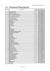
... Device Parameters 1 Read Buffer 4 Read DMA 4 Read DMA 4 Read DMA Ext 5 Read FPDMA Queued 1 Read Log Ext 1 Read Multiple 1 Read Multiple Ext 3 Read Native Max Address 3 Read Native Max Address Ext 1 Read Sector(s) 1 Read Sector(s) 1 Read Sector(s) Ext 3 Read Verify Sector(s) 3 Read Verify Sector(s) 3 Read Verify Sector(s) Ext 3 Recalibrate 2 Security Disable Password 3 Security Erase Prepare 2 Security Erase Unit 3 Security Freeze Lock 2 Security Set Password 2 Security Unlock 3 Seek 3 Sense Condition 3 Set Features Table 40 Command set Page 72 of 176 7K320 (SATA) OEM Specification Code...
... Device Parameters 1 Read Buffer 4 Read DMA 4 Read DMA 4 Read DMA Ext 5 Read FPDMA Queued 1 Read Log Ext 1 Read Multiple 1 Read Multiple Ext 3 Read Native Max Address 3 Read Native Max Address Ext 1 Read Sector(s) 1 Read Sector(s) 1 Read Sector(s) Ext 3 Read Verify Sector(s) 3 Read Verify Sector(s) 3 Read Verify Sector(s) Ext 3 Recalibrate 2 Security Disable Password 3 Security Erase Prepare 2 Security Erase Unit 3 Security Freeze Lock 2 Security Set Password 2 Security Unlock 3 Seek 3 Sense Condition 3 Set Features Table 40 Command set Page 72 of 176 7K320 (SATA) OEM Specification Code...

Specifications
Page 74
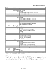
... Device Register is recommended for future compatibility.) B Option Bit. Disable Operations S.M.A.R.T. Enable/Disable Automatic Off-line (Set Features) Enable Write Cache Set Transfer Mode Enable Advanced Power Management feature Enable Power-Up in Standby feature Power-Up in Standby feature Disable use of Serial ATA feature Disable read look-ahead feature Disable reverting to power on Page 74 shows the sub-commands that the head number part of Serial ATA feature Enable read look-ahead feature Enable reverting to 1. Write Log Sector S.M.A.R.T. L LBA mode. Read Log Sector...
... Device Register is recommended for future compatibility.) B Option Bit. Disable Operations S.M.A.R.T. Enable/Disable Automatic Off-line (Set Features) Enable Write Cache Set Transfer Mode Enable Advanced Power Management feature Enable Power-Up in Standby feature Power-Up in Standby feature Disable use of Serial ATA feature Disable read look-ahead feature Disable reverting to power on Page 74 shows the sub-commands that the head number part of Serial ATA feature Enable read look-ahead feature Enable reverting to 1. Write Log Sector S.M.A.R.T. L LBA mode. Read Log Sector...
Specifications
Page 79
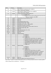
...Table 46 Device Configuration Overlay Data structure Note. Each byte is added with unsigned arithmetic, and overflow is supported 3-6 Maximum LBA address 7 Command set/feature set supported 15-9 Reserved 8 1 = 48-bit Addressing feature set supported 7 1 = Host Protected Area feature set supported 6 Reserved 5 Reserved 4 1 = Power-Up in Standby feature set supported 3 1 = Security feature set supported 2 1 = SMART error log supported 1 1 = SMART self-test supported 0 1 = SMART feature set supported 8 SATA feature 15-5 Reserved 4 1 = Software setting preservation supported...
...Table 46 Device Configuration Overlay Data structure Note. Each byte is added with unsigned arithmetic, and overflow is supported 3-6 Maximum LBA address 7 Command set/feature set supported 15-9 Reserved 8 1 = 48-bit Addressing feature set supported 7 1 = Host Protected Area feature set supported 6 Reserved 5 Reserved 4 1 = Power-Up in Standby feature set supported 3 1 = Security feature set supported 2 1 = SMART error log supported 1 1 = SMART self-test supported 0 1 = SMART feature set supported 8 SATA feature 15-5 Reserved 4 1 = Software setting preservation supported...
Specifications
Page 90
... vendor specific 12 (=0) Reserved 11 (=1) 1= IORDY Supported 10 (=1) 1= IORDY can be disabled 9 (=1) 1=LBA Supported 8 (=1) 1=DMA Supported * 7- 0 (=0) Reserved 50 4000H Capabilities 15 (=0) 0=the contents of word 50 are valid 14 (=1) 1=the contents of word 50 are valid 13- 2 (=0) Reserved 1 (=0) Obsolete 0 (=0) 1=the device has a minimum Standby timer value that is device specific 51 0200H * PIO data transfer cycle timing mode 52 0200H * DMA data transfer cycle timing mode Refer...
... vendor specific 12 (=0) Reserved 11 (=1) 1= IORDY Supported 10 (=1) 1= IORDY can be disabled 9 (=1) 1=LBA Supported 8 (=1) 1=DMA Supported * 7- 0 (=0) Reserved 50 4000H Capabilities 15 (=0) 0=the contents of word 50 are valid 14 (=1) 1=the contents of word 50 are valid 13- 2 (=0) Reserved 1 (=0) Obsolete 0 (=0) 1=the device has a minimum Standby timer value that is device specific 51 0200H * PIO data transfer cycle timing mode 52 0200H * DMA data transfer cycle timing mode Refer...
Specifications
Page 92
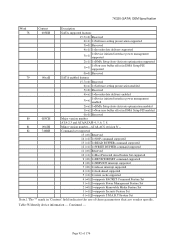
... initiated interface power management enabled 2(=x) 1=DMA Setup Auto-Activate optimization enabled 1(=x) 1=Non-zero buffer offset in DMA Setup FIS enabled 0(=0) Reserved 80 01FCH Major version number ATA-2.3 and ATA/ATAPI-4, 5, 6, 7, 8 81 0042H Minor version number-ATA8-ACS revision 3f -- 82 746BH Command set supported 15 (=0) Reserved 14 (=1) 1=NOP command supported 13 (=1) 1=READ BUFFER command supported 12 (=1) 1=WRITE BUFFER command supported 11 (=0) Reserved 10 (=1) 1=Host Protected Area Feature Set supported 9 (=0) 1=DEVICE RESET command supported 8 (=0) 1=SERVICE...
... initiated interface power management enabled 2(=x) 1=DMA Setup Auto-Activate optimization enabled 1(=x) 1=Non-zero buffer offset in DMA Setup FIS enabled 0(=0) Reserved 80 01FCH Major version number ATA-2.3 and ATA/ATAPI-4, 5, 6, 7, 8 81 0042H Minor version number-ATA8-ACS revision 3f -- 82 746BH Command set supported 15 (=0) Reserved 14 (=1) 1=NOP command supported 13 (=1) 1=READ BUFFER command supported 12 (=1) 1=WRITE BUFFER command supported 11 (=0) Reserved 10 (=1) 1=Host Protected Area Feature Set supported 9 (=0) 1=DEVICE RESET command supported 8 (=0) 1=SERVICE...
Specifications
Page 93
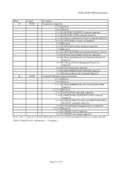
...CACHE EXT command supported 12 (=1) 1=FLUSH CACHE command supported 11 (=1) 1=Device Configuration Overlay command supported 10 (=1) 1=48-bit Address feature set supported 9 (=0) Reserved 8 (=1) 1=SET MAX security extension supported 7 (=0) Reserved 6 (=1) 1=SET FEATURES subcommand required to spin-up 5 (=1) 1=Power-Up In Standby feature set supported 4 (=0) 1=Removable Media Status Notification Feature Set supported 3 (=1) 1=Advanced Power Management Feature Set supported 2 (=0) 1=CFA Feature Set supported 1 (=0) 1=READ/WRITE DMA QUEUED supported 0 (=1) Download Microcode Command...
...CACHE EXT command supported 12 (=1) 1=FLUSH CACHE command supported 11 (=1) 1=Device Configuration Overlay command supported 10 (=1) 1=48-bit Address feature set supported 9 (=0) Reserved 8 (=1) 1=SET MAX security extension supported 7 (=0) Reserved 6 (=1) 1=SET FEATURES subcommand required to spin-up 5 (=1) 1=Power-Up In Standby feature set supported 4 (=0) 1=Removable Media Status Notification Feature Set supported 3 (=1) 1=Advanced Power Management Feature Set supported 2 (=0) 1=CFA Feature Set supported 1 (=0) 1=READ/WRITE DMA QUEUED supported 0 (=1) Download Microcode Command...
Specifications
Page 96
... 5 (=0) 1=Free-fall Control feature set is enabled 4 (=1) 1=Download Microcode with mode 3 is supported 3 (=0) 1=Read and Write DMA Ext GPL is supported 2 (=1) 1=WRITE UNCORRECTABLE is supported 1 (=0) 1=Write Read Verify feature set is enabled 0 (=0) Reserved 121-126 0000H Reserved 127 0000H Removable Media Status Notification feature set Note.1 The '*' mark in 'Content' field indicates the use of 176 DMA and PIO 98-99 0000H Streaming Performance Granularity 100-103 Note.2 Maximum user LBA address...
... 5 (=0) 1=Free-fall Control feature set is enabled 4 (=1) 1=Download Microcode with mode 3 is supported 3 (=0) 1=Read and Write DMA Ext GPL is supported 2 (=1) 1=WRITE UNCORRECTABLE is supported 1 (=0) 1=Write Read Verify feature set is enabled 0 (=0) Reserved 121-126 0000H Reserved 127 0000H Removable Media Status Notification feature set Note.1 The '*' mark in 'Content' field indicates the use of 176 DMA and PIO 98-99 0000H Streaming Performance Granularity 100-103 Note.2 Maximum user LBA address...
Specifications
Page 130
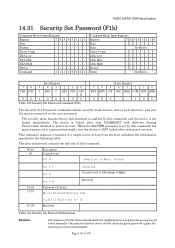
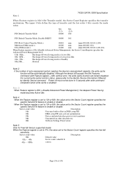
... the MASTER password is set by this command, the master password is registered internally, but the device is not locked immediately. Sector Count -------- 7K320 (SATA) OEM Specification 14.31 Security Set Password (F1h) Command Block Output Registers Register 76543210 Data -------- LBA Low -------- LBA Low -------- The security mode feature (device lock function) is enabled by this command, and the device is NOT locked after next COMRESET with Software Setting Preservation disabled or power on reset. This command requests a transfer of a single sector of data...
... the MASTER password is set by this command, the master password is registered internally, but the device is not locked immediately. Sector Count -------- 7K320 (SATA) OEM Specification 14.31 Security Set Password (F1h) Command Block Output Registers Register 76543210 Data -------- LBA Low -------- LBA Low -------- The security mode feature (device lock function) is enabled by this command, and the device is NOT locked after next COMRESET with Software Setting Preservation disabled or power on reset. This command requests a transfer of a single sector of data...
Specifications
Page 136
... Sector Count register specifies the specific Serial ATA feature to the Sector Count register specifies the free-fall Sensor supported model. Only for Free-fall sensitivity. BFh ... Although the device still accepts the Set Features command (with Feature register = 02h) without error, the write cache function will be done in -order data delivery 06h Software Settings Preservation Note 5. Power off must not be automatically disabled. When the Feature register is enabled...
... Sector Count register specifies the specific Serial ATA feature to the Sector Count register specifies the free-fall Sensor supported model. Only for Free-fall sensitivity. BFh ... Although the device still accepts the Set Features command (with Feature register = 02h) without error, the write cache function will be done in -order data delivery 06h Software Settings Preservation Note 5. Power off must not be automatically disabled. When the Feature register is enabled...
Specifications
Page 137
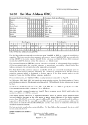
... IDX ERR 0V0 - - 0 0V The Set Max Address command overwrites the max LBA/CYL of HDD in status register. The Head number of 176 Output Parameters To The Device Feature Destination code for that LBA/CYL are ignored. 7K320 (SATA) OEM Specification 14.36 Set Max Address (F9h) Command Block Output Registers Register 76543210 Data -------- The device receives this command 01h SET MAX SET PASSWORD Page 137 of Device and LBA Low are rejected with 28-bit...
... IDX ERR 0V0 - - 0 0V The Set Max Address command overwrites the max LBA/CYL of HDD in status register. The Head number of 176 Output Parameters To The Device Feature Destination code for that LBA/CYL are ignored. 7K320 (SATA) OEM Specification 14.36 Set Max Address (F9h) Command Block Output Registers Register 76543210 Data -------- The device receives this command 01h SET MAX SET PASSWORD Page 137 of Device and LBA Low are rejected with 28-bit...


