
HP DTC Cabling and Racking Guide
Page 3
... Racking the Direct Distribution Panel 8-port DDP HP J2085A #102 20 Racking the Modem Distribution Panel HP J2085 #101 22 Front Mounting 22 Rear Mounting MDP Units 24 Racking the 24-port RJ45 Direct Distribution Panel HP J2085A #103 and the 16-port RJ45 DDP HP J2085A #105 26 Attaching an 8-port RJ45...with 88 ports in 1.1m rack 33 System and DTC 72MX with 184 ports in 1.6m rack 34 6 Connecting Asynchronous Devices 35 Overview 35 Rear view of a DTC 16xx with example connections 35 Rear View of a DTC 72MX with example connections 36 Connecting Asynchronous Devices 37 iii
... Racking the Direct Distribution Panel 8-port DDP HP J2085A #102 20 Racking the Modem Distribution Panel HP J2085 #101 22 Front Mounting 22 Rear Mounting MDP Units 24 Racking the 24-port RJ45 Direct Distribution Panel HP J2085A #103 and the 16-port RJ45 DDP HP J2085A #105 26 Attaching an 8-port RJ45...with 88 ports in 1.1m rack 33 System and DTC 72MX with 184 ports in 1.6m rack 34 6 Connecting Asynchronous Devices 35 Overview 35 Rear view of a DTC 16xx with example connections 35 Rear View of a DTC 72MX with example connections 36 Connecting Asynchronous Devices 37 iii

HP DTC Cabling and Racking Guide
Page 41
... to popular cabling systems. You will also find descriptions of the cables necessary for supported LAN cables and transceivers. The standard product (HP J2060A, J2062A) is shown. Rear view of one 8-port RJ45 panel and one Modem Distribution Panel is supplied with example connections This example illustrates a ThinLAN connection (AUI port unused...
... to popular cabling systems. You will also find descriptions of the cables necessary for supported LAN cables and transceivers. The standard product (HP J2060A, J2062A) is shown. Rear view of one 8-port RJ45 panel and one Modem Distribution Panel is supplied with example connections This example illustrates a ThinLAN connection (AUI port unused...

HP DTC Cabling and Racking Guide
Page 42
An 8-port Modem Distribution Panel and a 24-port Direct Distribution Panel are shown connected. 36 6 Overview Rear View of a DTC 72MX with example connections In this example, a DTC 72MX is illustrated with a ThinLAN connection.
An 8-port Modem Distribution Panel and a 24-port Direct Distribution Panel are shown connected. 36 6 Overview Rear View of a DTC 72MX with example connections In this example, a DTC 72MX is illustrated with a ThinLAN connection.

nPartition Administrator's Guide, Second Edition
Page 210
...on the external chassis at the rear of the power LEDs for Managing Hardware" (page 201). 1. HP-UX B.11.11 supports the rad command for the cabinet. options. On HP rp7405/rp7410, rp7420, rx7620, rp8400, rp8420, and rx8620 servers only, you must access HP-UX in the error logs and... system with the nPartition commands installed. To manage PCI slot attention indicators, you also can view the attention indicator for controlling PCI card slot attention indicators and other tasks. You can view the attention indicator for each PCI slot beneath the corresponding slot, on or off the LED...
...on the external chassis at the rear of the power LEDs for Managing Hardware" (page 201). 1. HP-UX B.11.11 supports the rad command for the cabinet. options. On HP rp7405/rp7410, rp7420, rx7620, rp8400, rp8420, and rx8620 servers only, you must access HP-UX in the error logs and... system with the nPartition commands installed. To manage PCI slot attention indicators, you also can view the attention indicator for controlling PCI card slot attention indicators and other tasks. You can view the attention indicator for each PCI slot beneath the corresponding slot, on or off the LED...
nPartition Administrator's Guide, Second Edition
Page 245
...I/O Expansion cabinet. - 2 - the top bay in the bay, as viewed from the cabinet rear: the left eight PCI card slots. - 1 - On HP Superdome servers, the chassis number is : - 0 - On HP Superdome servers, the cabinet number can be : - 0 - Chassis 0, which connects ... 0. On HP rp7405/rp7410, rp7420, rx7620, rp8400, rp8420, and rx8620 servers, the chassis number is : - 1 - an I /O chassis resides. On HP rp7405/rp7410, rp7420, rp7440, rx7620, rx7640, rp8400, rp8420, rp8440, rx8620, and rx8640 servers, the server cabinet number always is the left chassis as viewed when facing the...
...I/O Expansion cabinet. - 2 - the top bay in the bay, as viewed from the cabinet rear: the left eight PCI card slots. - 1 - On HP Superdome servers, the chassis number is : - 0 - On HP Superdome servers, the cabinet number can be : - 0 - Chassis 0, which connects ... 0. On HP rp7405/rp7410, rp7420, rx7620, rp8400, rp8420, and rx8620 servers, the chassis number is : - 1 - an I /O chassis resides. On HP rp7405/rp7410, rp7420, rp7440, rx7620, rx7640, rp8400, rp8420, rp8440, rx8620, and rx8640 servers, the server cabinet number always is the left chassis as viewed when facing the...

User Guide, Third Edition - hp rp7405/rp7410 Servers
Page 9
...Figure 2-18. Power Distribution 35 Figure 2-22. The ls Command Screen 42 Figure 2-26. hp rp7405/rp7410 Server (front view 2 Figure 1-2. Cell Board 7 Figure 1-6. Right-Front View of Conformity xi Figure 2. Preparing to the Rack 25 Figure 2-10. Inserting the Pins Into... the Cabinet 22 Figure 2-5. hp rp7410 8-Way Block Diagram 6 Figure 1-4. Left-Rear View of hp rp7405/rp7410 16 Figure 2-1. Removing the Polystraps and Cardboard 19 Figure 2-2. Server with Shipping Box Removed 23 Figure 2-7. Figures Figure 1. Attaching CMA to the Server 30 Figure 2-17. The du...
...Figure 2-18. Power Distribution 35 Figure 2-22. The ls Command Screen 42 Figure 2-26. hp rp7405/rp7410 Server (front view 2 Figure 1-2. Cell Board 7 Figure 1-6. Right-Front View of Conformity xi Figure 2. Preparing to the Rack 25 Figure 2-10. Inserting the Pins Into... the Cabinet 22 Figure 2-5. hp rp7410 8-Way Block Diagram 6 Figure 1-4. Left-Rear View of hp rp7405/rp7410 16 Figure 2-1. Removing the Polystraps and Cardboard 19 Figure 2-2. Server with Shipping Box Removed 23 Figure 2-7. Figures Figure 1. Attaching CMA to the Server 30 Figure 2-17. The du...

User Guide, Third Edition - hp rp7405/rp7410 Servers
Page 37
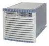
... cm fans are 15 cm (6.5-inch) fans. Four OLR system fan modules, externally attached to the chassis, are housed in the top rear portion of the product volume. Two fans are mounted on the front surface of the chassis and two are located in plastic carriers. Access...Chapter 1 15 The MP/SCSI MP Core I/O boards are required to power the server. They are located in two rows of three fans. Introduction Detailed hp rp7405/rp7410 Description Figure 1-10 Right-Front View of hp rp7405/rp7410 PCI cards Front panel display board PCI DC-to-DC converters Cell boards Bulk powers...
... cm fans are 15 cm (6.5-inch) fans. Four OLR system fan modules, externally attached to the chassis, are housed in the top rear portion of the product volume. Two fans are mounted on the front surface of the chassis and two are located in plastic carriers. Access...Chapter 1 15 The MP/SCSI MP Core I/O boards are required to power the server. They are located in two rows of three fans. Introduction Detailed hp rp7405/rp7410 Description Figure 1-10 Right-Front View of hp rp7405/rp7410 PCI cards Front panel display board PCI DC-to-DC converters Cell boards Bulk powers...

User Guide, Third Edition - hp rp7405/rp7410 Servers
Page 38
Figure 1-11 Left-Rear View of the chassis behind a removable side cover. Introduction Detailed hp rp7405/rp7410 Description Cell boards are accessed from the right side of hp rp7405/rp7410 System backplane MP Core I/O MP/SCSIs 16 Chapter 1
Figure 1-11 Left-Rear View of the chassis behind a removable side cover. Introduction Detailed hp rp7405/rp7410 Description Cell boards are accessed from the right side of hp rp7405/rp7410 System backplane MP Core I/O MP/SCSIs 16 Chapter 1

User Guide, Third Edition - hp rp7405/rp7410 Servers
Page 93
...all ESD safety precautions before attempting this procedure. The Fan assembly is a hot swappable component. Figure 4-10 Rear Smart Fan Assembly Locations FAN 2 FAN 3 LED Rear View LED Table 4-2 Rear Smart Fan Assembly LED Indications LED State On Green Flash Yellow Flash Red Off Meaning Fan is at speed ... than 6 seconds Fan is not installed or no power is applied to the server. Removal and Replacement Removing and Replacing a Rear Smart Fan Assembly Removing and Replacing a Rear Smart Fan Assembly The Rear Smart Fan Assembly is located in sync or not at speed and in the...
...all ESD safety precautions before attempting this procedure. The Fan assembly is a hot swappable component. Figure 4-10 Rear Smart Fan Assembly Locations FAN 2 FAN 3 LED Rear View LED Table 4-2 Rear Smart Fan Assembly LED Indications LED State On Green Flash Yellow Flash Red Off Meaning Fan is at speed ... than 6 seconds Fan is not installed or no power is applied to the server. Removal and Replacement Removing and Replacing a Rear Smart Fan Assembly Removing and Replacing a Rear Smart Fan Assembly The Rear Smart Fan Assembly is located in sync or not at speed and in the...

User Guide, Third Edition - hp rp7405/rp7410 Servers
Page 104
If no critical resources will be blinking. Step 4. On the server, you can view the PCI slots and slot LEDs from the PCI slot. Flip the ... selected card offline then click the OK button to click the OK button and cannot replace the card while HP-UX remains running. Note that the selected PCI card cannot be powered off ), and the slot's amber attention...to complete its critical resource analysis for future reference. Remove the top cover. Remove the card from the rear of the cabinet. Firmly pull up on the tabs on the nPartition before replacing the defective card. Step ...
If no critical resources will be blinking. Step 4. On the server, you can view the PCI slots and slot LEDs from the PCI slot. Flip the ... selected card offline then click the OK button to click the OK button and cannot replace the card while HP-UX remains running. Note that the selected PCI card cannot be powered off ), and the slot's amber attention...to complete its critical resource analysis for future reference. Remove the top cover. Remove the card from the rear of the cabinet. Firmly pull up on the tabs on the nPartition before replacing the defective card. Step ...

