
Notebook Tour Guide
Page 11
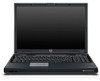
Lights Component 1 Wireless light (select models only) 2 Power lights* (2) 3 Caps lock light Description On: An integrated wireless device, such as a wireless local area network (LAN) device and/or a Bluetooth® device is turned on . (Continued) Notebook Tour 9 On: Caps lock is in hibernation. Blinking: The computer is on . On: The computer is off or in standby. Off: The computer is on.
Lights Component 1 Wireless light (select models only) 2 Power lights* (2) 3 Caps lock light Description On: An integrated wireless device, such as a wireless local area network (LAN) device and/or a Bluetooth® device is turned on . (Continued) Notebook Tour 9 On: Caps lock is in hibernation. Blinking: The computer is on . On: The computer is off or in standby. Off: The computer is on.
Notebook Tour Guide
Page 15
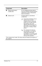
... optional printer, or a soft surface, such as a wireless local area network (LAN) device and/or a Bluetooth® device is normal for the internal fan to cool internal components. Ä To prevent overheating, do not obstruct vents. Notebook Tour 13 Use the computer only on the bottom of the computer. Provides airflow to...
... optional printer, or a soft surface, such as a wireless local area network (LAN) device and/or a Bluetooth® device is normal for the internal fan to cool internal components. Ä To prevent overheating, do not obstruct vents. Notebook Tour 13 Use the computer only on the bottom of the computer. Provides airflow to...

Notebook Tour Guide
Page 24
An optional device may need this information available when you contact Customer Care. Notebook Tour 22 This certificate is affixed to the bottom of the computer. ■ Modem approval label-Provides regulatory information about the modem and lists the ... Certificate of the countries in which the devices have been approved for use . You may be a wireless local area network (WLAN) device or an optional Bluetooth® device. Have this information when traveling internationally.
An optional device may need this information available when you contact Customer Care. Notebook Tour 22 This certificate is affixed to the bottom of the computer. ■ Modem approval label-Provides regulatory information about the modem and lists the ... Certificate of the countries in which the devices have been approved for use . You may be a wireless local area network (WLAN) device or an optional Bluetooth® device. Have this information when traveling internationally.

Notebook Tour Guide
Page 29
...15 Digital Media Slot, location 16 display release latch 11, 19 display switch, identifying 4 drives, optical 14 DVD button 6 E eject button, PC Card slot 16 environmental specifications 23 exhaust vents 13, 18 expansion port 2 15, 25 ExpressCard slot 14 external monitor port 15 F fn key ... 12 RJ-45 (network) 15 S-Video-out 15 K keypad keys 2 keys esc 2 fn 2 function 2 keypad 2 Windows applications 2 Windows logo 2 L labels Bluetooth 22 Microsoft Certificate of Authenticity 22 modem approval 22 regulatory 22 service tag 22 wireless certification 22 WLAN 22 latches battery pack release 17 display...
...15 Digital Media Slot, location 16 display release latch 11, 19 display switch, identifying 4 drives, optical 14 DVD button 6 E eject button, PC Card slot 16 environmental specifications 23 exhaust vents 13, 18 expansion port 2 15, 25 ExpressCard slot 14 external monitor port 15 F fn key ... 12 RJ-45 (network) 15 S-Video-out 15 K keypad keys 2 keys esc 2 fn 2 function 2 keypad 2 Windows applications 2 Windows logo 2 L labels Bluetooth 22 Microsoft Certificate of Authenticity 22 modem approval 22 regulatory 22 service tag 22 wireless certification 22 WLAN 22 latches battery pack release 17 display...
Notebook Tour Guide
Page 32
..., L.P. The only warranties for technical or editorial errors or omissions contained herein. Bluetooth is subject to change without notice. Notebook Tour First Edition October 2005 Document Part Number: 393523-001 Nothing herein should be liable for HP products and services are U.S. registered trademarks of its proprietor and used by Hewlett-...are set forth in the express warranty statements accompanying such products and services. The information contained herein is a trademark owned by its proprietor. HP shall not be construed as constituting an additional warranty.
..., L.P. The only warranties for technical or editorial errors or omissions contained herein. Bluetooth is subject to change without notice. Notebook Tour First Edition October 2005 Document Part Number: 393523-001 Nothing herein should be liable for HP products and services are U.S. registered trademarks of its proprietor and used by Hewlett-...are set forth in the express warranty statements accompanying such products and services. The information contained herein is a trademark owned by its proprietor. HP shall not be construed as constituting an additional warranty.

Maintenance and Service Guide
Page 2
... construed as constituting an additional warranty. AMD, Turion, and combinations thereof, are trademarks of Microsoft Corporation. registered trademarks of Advanced Micro Devices, Inc. Bluetooth is a trademark owned by its proprietor. Maintenance and Service Guide HP Pavilion dv8000 Notebook PC First Edition November 2005 Document Part Number: 403248-001 © Copyright 2005 Hewlett-Packard Development Company, L.P.
... construed as constituting an additional warranty. AMD, Turion, and combinations thereof, are trademarks of Microsoft Corporation. registered trademarks of Advanced Micro Devices, Inc. Bluetooth is a trademark owned by its proprietor. Maintenance and Service Guide HP Pavilion dv8000 Notebook PC First Edition November 2005 Document Part Number: 403248-001 © Copyright 2005 Hewlett-Packard Development Company, L.P.

Maintenance and Service Guide
Page 5
... 5.11 Keyboard Assembly Frame 5-24 5.12 LED Board 5-28 5.13 Keyboard 5-30 5.14 Display Assembly 5-32 5.15 Top Cover 5-43 5.16 System Board 5-50 5.17 Bluetooth Module 5-57 5.18 Modem Connector Cable 5-60 5.19 USB Board 5-62 5.20 Speakers 5-64 5.21 Heat Sink 5-67 5.22 Processor 5-70 5.23 Fan Assembly 5-72...
... 5.11 Keyboard Assembly Frame 5-24 5.12 LED Board 5-28 5.13 Keyboard 5-30 5.14 Display Assembly 5-32 5.15 Top Cover 5-43 5.16 System Board 5-50 5.17 Bluetooth Module 5-57 5.18 Modem Connector Cable 5-60 5.19 USB Board 5-62 5.20 Speakers 5-64 5.21 Heat Sink 5-67 5.22 Processor 5-70 5.23 Fan Assembly 5-72...

Maintenance and Service Guide
Page 65
...(1.6-GHz) 393579-001 393578-001 395744-001 395743-001 ExpressCard assembly 403828-001 Plastics Kit 403812-001 Includes: ExpressCard slot bezel PC Card slot bezel Memory shield Hard drive cover (includes 3 captive screws) Memory/Mini PCI module compartment cover (includes 2 captive ...screws) Computer feet (not illustrated) RTC battery 403819-001 Bluetooth® module (includes Bluetooth module cable) 397922-001 PC Card assembly 403835-001 Base enclosure 403824-001 Hard drives (include frame and connector) 7200 rpm, 100-GB...
...(1.6-GHz) 393579-001 393578-001 395744-001 395743-001 ExpressCard assembly 403828-001 Plastics Kit 403812-001 Includes: ExpressCard slot bezel PC Card slot bezel Memory shield Hard drive cover (includes 3 captive screws) Memory/Mini PCI module compartment cover (includes 2 captive ...screws) Computer feet (not illustrated) RTC battery 403819-001 Bluetooth® module (includes Bluetooth module cable) 397922-001 PC Card assembly 403835-001 Base enclosure 403824-001 Hard drives (include frame and connector) 7200 rpm, 100-GB...

Maintenance and Service Guide
Page 71
3.5 Cable Kit Illustrated Parts Catalog Table 3-4 Cable Kit Spare Part Number Information Item 1 2 3 4 5 Description Cable Kit, includes: TouchPad cable Modem connector cable Bluetooth module cable USB board cable Power connector cable Spare Part Number 403814-001 Maintenance and Service Guide 3-13
3.5 Cable Kit Illustrated Parts Catalog Table 3-4 Cable Kit Spare Part Number Information Item 1 2 3 4 5 Description Cable Kit, includes: TouchPad cable Modem connector cable Bluetooth module cable USB board cable Power connector cable Spare Part Number 403814-001 Maintenance and Service Guide 3-13

Maintenance and Service Guide
Page 75
...-001 403790-001 403791-001 Table 3-7 Sequential Part Number Listing Description USB travel mouse USB digital drive Wired headset with volume control HP remote control All-in-one media cable Audio Y-cable 2 802.11b/g WLAN Mini PCI communications module for use in North America 802...AMD Turion 64 ML-30 (1.6-GHz) processor (includes thermal paste) AMD Turion 64 ML-32 (1.8-GHz) processor (includes thermal paste) Bluetooth wireless module (includes Bluetooth module cable) 256-MB memory module System board 802.11a/b/g WLAN Mini PCI communications module for use in North America Maintenance and ...
...-001 403790-001 403791-001 Table 3-7 Sequential Part Number Listing Description USB travel mouse USB digital drive Wired headset with volume control HP remote control All-in-one media cable Audio Y-cable 2 802.11b/g WLAN Mini PCI communications module for use in North America 802...AMD Turion 64 ML-30 (1.6-GHz) processor (includes thermal paste) AMD Turion 64 ML-32 (1.8-GHz) processor (includes thermal paste) Bluetooth wireless module (includes Bluetooth module cable) 256-MB memory module System board 802.11a/b/g WLAN Mini PCI communications module for use in North America Maintenance and ...

Maintenance and Service Guide
Page 90
... Description Keyboard Assembly Frame LED Board Keyboard Display Assembly 6.15 Top Cover 6.16 System Board 6.17 Bluetooth Module 6.18 Modem Connector Cable 6.19 USB Board 6.20 Speakers 6.21 Heat Sink 6.22 Processor 6.23 Fan Assembly 6.24 PC Card Assembly # of Screws Removed 2 4 5 6 to remove the display assembly 6 to remove the display bezel...
... Description Keyboard Assembly Frame LED Board Keyboard Display Assembly 6.15 Top Cover 6.16 System Board 6.17 Bluetooth Module 6.18 Modem Connector Cable 6.19 USB Board 6.20 Speakers 6.21 Heat Sink 6.22 Processor 6.23 Fan Assembly 6.24 PC Card Assembly # of Screws Removed 2 4 5 6 to remove the display assembly 6 to remove the display bezel...

Maintenance and Service Guide
Page 140
Removal and Replacement Procedures 8. Disconnect the following cables from the system board: 1 Modem cable 2 Bluetooth module cable 3 USB board cable Disconnecting the Modem, Bluetooth Module, and USB Board Cables 5-54 Maintenance and Service Guide
Removal and Replacement Procedures 8. Disconnect the following cables from the system board: 1 Modem cable 2 Bluetooth module cable 3 USB board cable Disconnecting the Modem, Bluetooth Module, and USB Board Cables 5-54 Maintenance and Service Guide

Maintenance and Service Guide
Page 143
Memory/Mini PCI module compartment cover (Section 5.6) c. Hard drive (Section 5.4) b. Optical drive (Section 5.9) d. Keyboard assembly frame (Section 5.11) f. Top cover (Section 5.15) Maintenance and Service Guide 5-57 Prepare the computer for disassembly (Section 5.3), and then remove the following components: a. Switch cover (Section 5.10) e. Removal and Replacement Procedures 5.17 Bluetooth Module Bluetooth Module Spare Part Number Information Bluetooth module (includes Bluetooth module cable) 1. Display assembly (Section 5.14) g.
Memory/Mini PCI module compartment cover (Section 5.6) c. Hard drive (Section 5.4) b. Optical drive (Section 5.9) d. Keyboard assembly frame (Section 5.11) f. Top cover (Section 5.15) Maintenance and Service Guide 5-57 Prepare the computer for disassembly (Section 5.3), and then remove the following components: a. Switch cover (Section 5.10) e. Removal and Replacement Procedures 5.17 Bluetooth Module Bluetooth Module Spare Part Number Information Bluetooth module (includes Bluetooth module cable) 1. Display assembly (Section 5.14) g.

Maintenance and Service Guide
Page 144
Disconnect the Bluetooth module cable 3 from the base enclosure 2. 4. Removal and Replacement Procedures 2. Remove the two Phillips PM2.0×4.0 screws 1 that secure the Bluetooth module to the base enclosure 3. Remove the Bluetooth module from the Bluetooth module. Removing the Bluetooth Module 5-58 Maintenance and Service Guide
Disconnect the Bluetooth module cable 3 from the base enclosure 2. 4. Removal and Replacement Procedures 2. Remove the two Phillips PM2.0×4.0 screws 1 that secure the Bluetooth module to the base enclosure 3. Remove the Bluetooth module from the Bluetooth module. Removing the Bluetooth Module 5-58 Maintenance and Service Guide

Maintenance and Service Guide
Page 145
... 403814-001. Maintenance and Service Guide 5-59 Removal and Replacement Procedures 5. Remove the Bluetooth module cable 4 from the clip in the base enclosure. ✎ The Bluetooth module cable is included with the Bluetooth module and is also available in the base enclosure. 7. Removing the Bluetooth Module Cable Reverse the above procedure to the right. 6.
... 403814-001. Maintenance and Service Guide 5-59 Removal and Replacement Procedures 5. Remove the Bluetooth module cable 4 from the clip in the base enclosure. ✎ The Bluetooth module cable is included with the Bluetooth module and is also available in the base enclosure. 7. Removing the Bluetooth Module Cable Reverse the above procedure to the right. 6.

Maintenance and Service Guide
Page 222
Length Thread Width Black 13 4.0 mm 2.0 mm 4.0 mm Where used: 2 screws that secure the Bluetooth module to the computer (documented in Section 5.17) Phillips PM2.0×4.0 Screw Locations C-30 Maintenance and Service Guide Screw Listing Table C-8 Phillips PM2.0×4.0 Screw (Continued) Head mm Color Qty.
Length Thread Width Black 13 4.0 mm 2.0 mm 4.0 mm Where used: 2 screws that secure the Bluetooth module to the computer (documented in Section 5.17) Phillips PM2.0×4.0 Screw Locations C-30 Maintenance and Service Guide Screw Listing Table C-8 Phillips PM2.0×4.0 Screw (Continued) Head mm Color Qty.

Maintenance and Service Guide
Page 239
... part number 3-7, 3-19 battery bay 1-13, 1-22 battery light 1-7 battery pack removal 5-6 spare part number 3-9, 3-18, 5-5 specifications 6-7 battery release latch 1-22 Bluetooth module removal 5-57 spare part number 3-7, 3-17, 5-57 Bluetooth module cable illustrated 3-13 removal 5-59 bottom components 1-22 Bracket Kit contents 3-5, 3-19 spare part number 3-5, 3-19 C Cable Kit components 3-13...
... part number 3-7, 3-19 battery bay 1-13, 1-22 battery light 1-7 battery pack removal 5-6 spare part number 3-9, 3-18, 5-5 specifications 6-7 battery release latch 1-22 Bluetooth module removal 5-57 spare part number 3-7, 3-17, 5-57 Bluetooth module cable illustrated 3-13 removal 5-59 bottom components 1-22 Bracket Kit contents 3-5, 3-19 spare part number 3-5, 3-19 C Cable Kit components 3-13...

HP Pavilion dv8200 Notebook PC, HP Pavilion dv8000 Notebook PC - Maintenance and Service Guide
Page 2
© Copyright 2005, 2006 Hewlett-Packard Development Company, L.P. HP shall not be construed as constituting an additional warranty. Bluetooth is subject to change without notice. Nothing herein should be liable for HP products and services are U.S. registered trademarks of Advanced Micro Devices, Inc. The only...is a trademark of its proprietor and used by Hewlett-Packard Company under license. Maintenance and Service Guide HP Pavilion dv8200 Notebook PC HP Pavilion dv8000 Notebook PC Second Edition: June 2006 First Edition: November 2005 Document Part Number: 403248-002
© Copyright 2005, 2006 Hewlett-Packard Development Company, L.P. HP shall not be construed as constituting an additional warranty. Bluetooth is subject to change without notice. Nothing herein should be liable for HP products and services are U.S. registered trademarks of Advanced Micro Devices, Inc. The only...is a trademark of its proprietor and used by Hewlett-Packard Company under license. Maintenance and Service Guide HP Pavilion dv8200 Notebook PC HP Pavilion dv8000 Notebook PC Second Edition: June 2006 First Edition: November 2005 Document Part Number: 403248-002

HP Pavilion dv8200 Notebook PC, HP Pavilion dv8000 Notebook PC - Maintenance and Service Guide
Page 5
... 5.11 Keyboard Assembly Frame 5-23 5.12 LED Board 5-27 5.13 Keyboard 5-29 5.14 Display Assembly 5-31 5.15 Top Cover 5-43 5.16 System Board 5-50 5.17 Bluetooth Module 5-57 5.18 Modem Connector Cable 5-60 5.19 USB Board 5-62 5.20 Speakers 5-64 5.21 Heat Sink 5-67 5.22 Processor 5-70 5.23 Fan Assembly 5-72...
... 5.11 Keyboard Assembly Frame 5-23 5.12 LED Board 5-27 5.13 Keyboard 5-29 5.14 Display Assembly 5-31 5.15 Top Cover 5-43 5.16 System Board 5-50 5.17 Bluetooth Module 5-57 5.18 Modem Connector Cable 5-60 5.19 USB Board 5-62 5.20 Speakers 5-64 5.21 Heat Sink 5-67 5.22 Processor 5-70 5.23 Fan Assembly 5-72...

HP Pavilion dv8200 Notebook PC, HP Pavilion dv8000 Notebook PC - Maintenance and Service Guide
Page 35
... system. Enable/disable: ■ USB Port. ■ 1394 Port. ■ CardBus Slot. Maintenance and Service Guide 2-5 Enable/disable: ■ Embedded WLAN Device Radio. ■ Embedded Bluetooth Device Radio. ■ LAN/WLAN Switching. ■ Wake on AC Power. ■ Data Execution Prevention. ■ LAN Power save. Troubleshooting Selecting from Off.
... system. Enable/disable: ■ USB Port. ■ 1394 Port. ■ CardBus Slot. Maintenance and Service Guide 2-5 Enable/disable: ■ Embedded WLAN Device Radio. ■ Embedded Bluetooth Device Radio. ■ LAN/WLAN Switching. ■ Wake on AC Power. ■ Data Execution Prevention. ■ LAN Power save. Troubleshooting Selecting from Off.


