Safety and Regulatory Information Desktops, Thin Clients, and Personal Workstations
Page 28
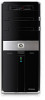
... 2-2 Toxic and Hazardous Substances and Elements Part Name Lead (Pb) Mercury (Hg) Cadmium (Cd) Hexavalent Chromium (Cr(VI)) Polybrominated biphenyls (PBB) Polybrominated diphenyl ethers (PBDE) Motherboard, processor and heat sink X O O O O O 22 Chapter 2 Regulatory Agency Notices ENWW
... 2-2 Toxic and Hazardous Substances and Elements Part Name Lead (Pb) Mercury (Hg) Cadmium (Cd) Hexavalent Chromium (Cr(VI)) Polybrominated biphenyls (PBB) Polybrominated diphenyl ethers (PBDE) Motherboard, processor and heat sink X O O O O O 22 Chapter 2 Regulatory Agency Notices ENWW

Upgrade and Service
Page 40
The plugs on the drive. MASTER SLAVE To CPU For plugs with the motherboard model in the cage: IMPORTANT: Recording the plug locations when there are filled first, starting with ... the memory socket to the processor (1) on your computer. 17 Disconnect the cables from the hard disk drive in your computer motherboard. Removing and Replacing Memory The blue sockets are multiple drives helps ensure you correctly replace the connections. For plugs without a latch...each plug, and then pull the plug (2 or 4) from the connector. 18 Locate the memory sockets on the motherboard.
The plugs on the drive. MASTER SLAVE To CPU For plugs with the motherboard model in the cage: IMPORTANT: Recording the plug locations when there are filled first, starting with ... the memory socket to the processor (1) on your computer. 17 Disconnect the cables from the hard disk drive in your computer motherboard. Removing and Replacing Memory The blue sockets are multiple drives helps ensure you correctly replace the connections. For plugs without a latch...each plug, and then pull the plug (2 or 4) from the connector. 18 Locate the memory sockets on the motherboard.

Upgrade and Service
Page 41
... tab that meet or exceed your original computer specifications. Removing and Replacing Memory 7 Hewlett-Packard always provides quality parts that matches the notch on the motherboard. 1 Touching only the top edge of memory has a different notch position. NOTE: Each type of the memory module, locate the notch on the bottom edge...
... tab that meet or exceed your original computer specifications. Removing and Replacing Memory 7 Hewlett-Packard always provides quality parts that matches the notch on the motherboard. 1 Touching only the top edge of memory has a different notch position. NOTE: Each type of the memory module, locate the notch on the bottom edge...
Getting Started
Page 13
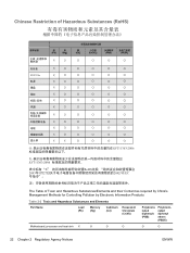
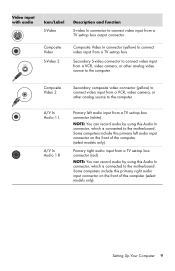
...from a TV set -top box connector (white). NOTE: You can record audio by using this Audio In connector, which is connected to the motherboard. Secondary S-video connector to connect video input from a VCR, video camera, or other analog video source to the computer. NOTE: You can... record audio by using this Audio In connector, which is connected to the motherboard. Setting Up Your Computer 9 Some computers include this primary right audio input connector on the front of the computer (select models only). ...
...from a TV set -top box connector (white). NOTE: You can record audio by using this Audio In connector, which is connected to the motherboard. Secondary S-video connector to connect video input from a VCR, video camera, or other analog video source to the computer. NOTE: You can... record audio by using this Audio In connector, which is connected to the motherboard. Setting Up Your Computer 9 Some computers include this primary right audio input connector on the front of the computer (select models only). ...
Getting Started
Page 14
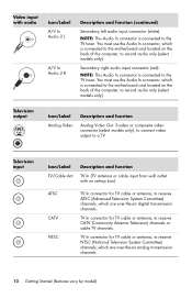
...tuner. NOTE: This Audio In connector is connected to the TV tuner. You must use the Audio In connector, which is connected to the motherboard and located on the back of the computer, to record audio only (select models only). Television output Icon/Label Analog Video Description and function Analog... channels. TV In connector for TV cable or antenna, to a TV. You must use the Audio In connector, which is connected to the motherboard and located on the back of the computer, to record audio only (select models only). ATSC CATV NTSC TV In connector for TV cable or...
...tuner. NOTE: This Audio In connector is connected to the TV tuner. You must use the Audio In connector, which is connected to the motherboard and located on the back of the computer, to record audio only (select models only). Television output Icon/Label Analog Video Description and function Analog... channels. TV In connector for TV cable or antenna, to a TV. You must use the Audio In connector, which is connected to the motherboard and located on the back of the computer, to record audio only (select models only). ATSC CATV NTSC TV In connector for TV cable or...
Upgrading and Servicing Guide
Page 18
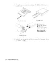
C - Connect to the back of the HP Pocket Media Drive bay or hard disk drive. Pocket Media Drive Serial ATA drive A - 4 Connect the power and data cables to the computer motherboard. Connect to a primary hard disk drive. Connect to a secondary hard disk drive (select models only). B - Parallel ATA drive 5 Replace the front and side panels, and close the computer. See "Opening and Closing the Computer" on page 1. 14 Upgrading and Servicing Guide
C - Connect to the back of the HP Pocket Media Drive bay or hard disk drive. Pocket Media Drive Serial ATA drive A - 4 Connect the power and data cables to the computer motherboard. Connect to a primary hard disk drive. Connect to a secondary hard disk drive (select models only). B - Parallel ATA drive 5 Replace the front and side panels, and close the computer. See "Opening and Closing the Computer" on page 1. 14 Upgrading and Servicing Guide
Upgrading and Servicing Guide
Page 24
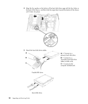
B - Connect to a primary hard disk drive. Serial ATA drive 20 Upgrading and Servicing Guide C - 4 Align the four guides on the bottom of the hard disk drive cage with the four holes on the back of the chassis, and then slide the cage down toward the bottom of the chassis until it locks into place. 5 Attach the hard disk drive cables. Parallel ATA drive A - Connect to a secondary hard disk drive (select models only). Connect to the computer motherboard.
B - Connect to a primary hard disk drive. Serial ATA drive 20 Upgrading and Servicing Guide C - 4 Align the four guides on the bottom of the hard disk drive cage with the four holes on the back of the chassis, and then slide the cage down toward the bottom of the chassis until it locks into place. 5 Attach the hard disk drive cables. Parallel ATA drive A - Connect to a secondary hard disk drive (select models only). Connect to the computer motherboard.

Upgrading and Servicing Guide
Page 26
... one or more memory modules installed, but you have. The exact number of sockets and the type of memory module could damage your computer. The motherboard contains sockets for specific memory module information and specifications, go to the Web site listed in -line memory modules). WARNING: Using the wrong type of...
... one or more memory modules installed, but you have. The exact number of sockets and the type of memory module could damage your computer. The motherboard contains sockets for specific memory module information and specifications, go to the Web site listed in -line memory modules). WARNING: Using the wrong type of...

Upgrading and Servicing Guide
Page 28
Always use the retaining clips to touch any cabling out of the way, if necessary. 7 Push down the retaining clip on the motherboard. WARNING: Do not pull the memory module out of the memory socket. CAUTION: When handling a memory module, be careful not to remove the module. 8 Lift the memory module out of the memory socket. 24 Upgrading and Servicing Guide Doing so may damage the module. 6 Move any of the contacts. 5 Locate the memory sockets on each end of the memory socket until the module pops out of the socket.
Always use the retaining clips to touch any cabling out of the way, if necessary. 7 Push down the retaining clip on the motherboard. WARNING: Do not pull the memory module out of the memory socket. CAUTION: When handling a memory module, be careful not to remove the module. 8 Lift the memory module out of the memory socket. 24 Upgrading and Servicing Guide Doing so may damage the module. 6 Move any of the contacts. 5 Locate the memory sockets on each end of the memory socket until the module pops out of the socket.

Upgrading and Servicing Guide
Page 32
... cover. See "Opening and Closing the Computer" on page 1. 2 Gently lay the computer on its side. 3 On the back of the sharp edges on the motherboard.
... cover. See "Opening and Closing the Computer" on page 1. 2 Gently lay the computer on its side. 3 On the back of the sharp edges on the motherboard.
Upgrading and Servicing Guide
Page 35
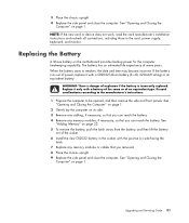
... the chassis upright. 9 Replace the side panel and close the computer. See "Opening and Closing the Computer" on page 1. 2 Gently lay the computer on the motherboard provides backup power for the computer timekeeping capability.
... the chassis upright. 9 Replace the side panel and close the computer. See "Opening and Closing the Computer" on page 1. 2 Gently lay the computer on the motherboard provides backup power for the computer timekeeping capability.

