Safety and Regulatory Information Desktops, Thin Clients, and Personal Workstations
Page 28
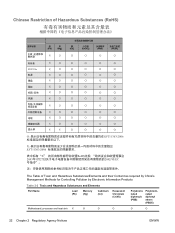
... 2-2 Toxic and Hazardous Substances and Elements Part Name Lead (Pb) Mercury (Hg) Cadmium (Cd) Hexavalent Chromium (Cr(VI)) Polybrominated biphenyls (PBB) Polybrominated diphenyl ethers (PBDE) Motherboard, processor and heat sink X O O O O O 22 Chapter 2 Regulatory Agency Notices ENWW
... 2-2 Toxic and Hazardous Substances and Elements Part Name Lead (Pb) Mercury (Hg) Cadmium (Cd) Hexavalent Chromium (Cr(VI)) Polybrominated biphenyls (PBB) Polybrominated diphenyl ethers (PBDE) Motherboard, processor and heat sink X O O O O O 22 Chapter 2 Regulatory Agency Notices ENWW
Warranty
Page 1
... for quicker help when you during the first year of the three-year warranty. Parts Limitations All components are provided to the following parts: motherboard, processor, memory, hard disk drive, graphics card, power supply, and LCD monitor. To obtain Hardware Warranty Repair Service, call the Customer Care... details), which are a few limitations and exclusions to fix your PC; You must be repaired or to have parts replaced, the HP Customer Care Center will make arrangements to this allows for repair in the Warranty and Support Guide. this warranty (as well as described...
... for quicker help when you during the first year of the three-year warranty. Parts Limitations All components are provided to the following parts: motherboard, processor, memory, hard disk drive, graphics card, power supply, and LCD monitor. To obtain Hardware Warranty Repair Service, call the Customer Care... details), which are a few limitations and exclusions to fix your PC; You must be repaired or to have parts replaced, the HP Customer Care Center will make arrangements to this allows for repair in the Warranty and Support Guide. this warranty (as well as described...
Getting Started
Page 13
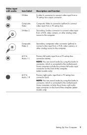
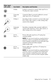
... 2 Secondary composite video connector (yellow) to connect video input from a VCR, video camera, or other analog video source to the motherboard. Some computers include this Audio In connector, which is connected to the computer. NOTE: You can record audio by using this primary ...set -top box output connector. Secondary S-video connector to the computer. Composite Video S-Video 2 Composite Video In connector (yellow) to the motherboard. Some computers include this Audio In connector, which is connected to connect video input from a TV set -top box. NOTE: You can...
... 2 Secondary composite video connector (yellow) to connect video input from a VCR, video camera, or other analog video source to the motherboard. Some computers include this Audio In connector, which is connected to the computer. NOTE: You can record audio by using this primary ...set -top box output connector. Secondary S-video connector to the computer. Composite Video S-Video 2 Composite Video In connector (yellow) to the motherboard. Some computers include this Audio In connector, which is connected to connect video input from a TV set -top box. NOTE: You can...
Getting Started
Page 14
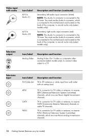
...receive CATV (Community Antenna Television) channels or cable TV channels. You must use the Audio In connector, which is connected to the motherboard and located on the back of the computer, to record audio only (select models only). Television input Icon/Label TV/Cable Ant... 2 R Description and function (continued) Secondary left audio input connector (white). You must use the Audio In connector, which is connected to the motherboard and located on the back of the computer, to record audio only (select models only). TV In connector for TV cable or antenna, to a...
...receive CATV (Community Antenna Television) channels or cable TV channels. You must use the Audio In connector, which is connected to the motherboard and located on the back of the computer, to record audio only (select models only). Television input Icon/Label TV/Cable Ant... 2 R Description and function (continued) Secondary left audio input connector (white). You must use the Audio In connector, which is connected to the motherboard and located on the back of the computer, to record audio only (select models only). TV In connector for TV cable or antenna, to a...
Getting Started
Page 89
Some computers include this Audio In connector, which is connected to the motherboard. Setting Up Your Computer 9 A/V In Audio 1 L A/V In Audio 1 R Primary left audio input connector on the front of the computer (select models only). Primary right audio ... using this primary left audio input from a TV set -top box connector (white). Some computers include this Audio In connector, which is connected to the motherboard. NOTE: You can record audio by using this primary right audio input connector on the front of the computer (select models only).
Some computers include this Audio In connector, which is connected to the motherboard. Setting Up Your Computer 9 A/V In Audio 1 L A/V In Audio 1 R Primary left audio input connector on the front of the computer (select models only). Primary right audio ... using this primary left audio input from a TV set -top box connector (white). Some computers include this Audio In connector, which is connected to the motherboard. NOTE: You can record audio by using this primary right audio input connector on the front of the computer (select models only).

Getting Started
Page 90
...ATSC CATV NTSC TV In connector for TV cable or antenna, to receive ATSC (Advanced Television System Committee) channels, which is connected to the motherboard and located on the back of the computer, to the TV tuner. Television input Icon/Label TV/Cable Ant Description and function TV In (... connector (white). TV In connector for TV cable or antenna, to receive NTSC (National Television System Committee) channels, which is connected to the motherboard and located on the back of the computer, to the TV tuner. You must use the Audio In connector, which are over -the-air ...
...ATSC CATV NTSC TV In connector for TV cable or antenna, to receive ATSC (Advanced Television System Committee) channels, which is connected to the motherboard and located on the back of the computer, to the TV tuner. Television input Icon/Label TV/Cable Ant Description and function TV In (... connector (white). TV In connector for TV cable or antenna, to receive NTSC (National Television System Committee) channels, which is connected to the motherboard and located on the back of the computer, to the TV tuner. You must use the Audio In connector, which are over -the-air ...

Getting Started
Page 13
... from a TV set-top box output connector. Some computers include this Audio In connector, which is connected to the motherboard. Some computers include this Audio In connector, which is connected to the motherboard. NOTE: You can record audio by using this primary right audio input connector on the front of the computer...
... from a TV set-top box output connector. Some computers include this Audio In connector, which is connected to the motherboard. Some computers include this Audio In connector, which is connected to the motherboard. NOTE: You can record audio by using this primary right audio input connector on the front of the computer...

Getting Started
Page 14
... ATSC CATV NTSC TV In connector for TV cable or antenna, to receive ATSC (Advanced Television System Committee) channels, which is connected to the motherboard and located on the back of the computer, to the TV tuner. Secondary right audio input connector (red). Television output Icon/Label Analog Video ...select models only). TV In connector for TV cable or antenna, to receive NTSC (National Television System Committee) channels, which is connected to the motherboard and located on the back of the computer, to the TV tuner. TV In connector for TV cable or antenna, to a TV.
... ATSC CATV NTSC TV In connector for TV cable or antenna, to receive ATSC (Advanced Television System Committee) channels, which is connected to the motherboard and located on the back of the computer, to the TV tuner. Secondary right audio input connector (red). Television output Icon/Label Analog Video ...select models only). TV In connector for TV cable or antenna, to receive NTSC (National Television System Committee) channels, which is connected to the motherboard and located on the back of the computer, to the TV tuner. TV In connector for TV cable or antenna, to a TV.

Upgrade and Service
Page 46
Removing and Replacing Memory NOTE: The location and number of the socket. 4 537486-001 - 7 Lay the computer on the side. 9 Push down the retaining clip on each end of the memory socket to release the memory module. 8 Locate the memory sockets on your computer. 10 Touching only the top edge of the memory module, lift it out of memory sockets may vary with the motherboard model in your computer motherboard.
Removing and Replacing Memory NOTE: The location and number of the socket. 4 537486-001 - 7 Lay the computer on the side. 9 Push down the retaining clip on each end of the memory socket to release the memory module. 8 Locate the memory sockets on your computer. 10 Touching only the top edge of the memory module, lift it out of memory sockets may vary with the motherboard model in your computer motherboard.

Upgrading and Servicing Guide
Page 20
... click Search. WARNING: Handle the memory module with care. Be careful to http://www.hp.com/support in -line memory modules). Avoid touching the memory chips. 16 Upgrading and Servicing Guide Removing and Replacing Memory The motherboard contains one or two memory module sockets for specific memory module information and specifications: 1 Go...
... click Search. WARNING: Handle the memory module with care. Be careful to http://www.hp.com/support in -line memory modules). Avoid touching the memory chips. 16 Upgrading and Servicing Guide Removing and Replacing Memory The motherboard contains one or two memory module sockets for specific memory module information and specifications: 1 Go...
Upgrading and Servicing Guide
Page 21
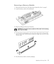
See "Removing an Optical Disc Drive" on page 9. 2 Locate the memory socket on the ends of the socket until the memory module pops out of the socket. WARNING: Do not pull the memory module out of the way, if necessary. Hold the memory module by its edges only, as you lift it away from the socket. 5 Store the memory module in antistatic packaging. Use the retaining clips to eject the module. 4 Push down the two retaining clips on the motherboard. 3 Move any cabling out of the socket. Upgrading and Servicing Guide 17 Removing a Memory Module 1 Remove the optical disc drive.
See "Removing an Optical Disc Drive" on page 9. 2 Locate the memory socket on the ends of the socket until the memory module pops out of the socket. WARNING: Do not pull the memory module out of the way, if necessary. Hold the memory module by its edges only, as you lift it away from the socket. 5 Store the memory module in antistatic packaging. Use the retaining clips to eject the module. 4 Push down the two retaining clips on the motherboard. 3 Move any cabling out of the socket. Upgrading and Servicing Guide 17 Removing a Memory Module 1 Remove the optical disc drive.
Upgrading and Servicing Guide
Page 24
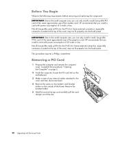
...of 25 watts or less. IMPORTANT: Due to the card, and then disconnect them. 4 Remove the screw on the modem card bracket holder on the motherboard. 3 Make a note of any internal cables attached to the small computer size, you can only install a small, low-profile PCI card of the same... approximate size of the modem card. Not all low-profile cards will fit into the back panel. This procedure requires a Phillips screwdriver. HP recommends that you install a card with power consumption of 5 watts or less. Not all low-profile cards will fit into the back panel. Some...
...of 25 watts or less. IMPORTANT: Due to the card, and then disconnect them. 4 Remove the screw on the modem card bracket holder on the motherboard. 3 Make a note of any internal cables attached to the small computer size, you can only install a small, low-profile PCI card of the same... approximate size of the modem card. Not all low-profile cards will fit into the back panel. This procedure requires a Phillips screwdriver. HP recommends that you install a card with power consumption of 5 watts or less. Not all low-profile cards will fit into the back panel. Some...
Upgrading and Servicing Guide
Page 26
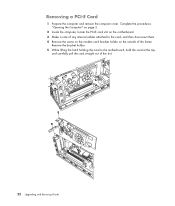
Remove the bracket holder. 5 While lifting the latch holding the card to the card, and then disconnect them. 4 Remove the screw on the modem card bracket holder on the outside of the slot. 22 Upgrading and Servicing Guide Removing a PCI-E Card 1 Prepare the computer and remove the computer cover. Complete the procedures "Opening the Computer" on page 2. 2 Inside the computer, locate the PCI-E card slot on the motherboard. 3 Make a note of any internal cables attached to the motherboard, hold the card at the top, and carefully pull the card straight out of the frame.
Remove the bracket holder. 5 While lifting the latch holding the card to the card, and then disconnect them. 4 Remove the screw on the modem card bracket holder on the outside of the slot. 22 Upgrading and Servicing Guide Removing a PCI-E Card 1 Prepare the computer and remove the computer cover. Complete the procedures "Opening the Computer" on page 2. 2 Inside the computer, locate the PCI-E card slot on the motherboard. 3 Make a note of any internal cables attached to the motherboard, hold the card at the top, and carefully pull the card straight out of the frame.

Upgrading and Servicing Guide
Page 28
.... Complete the procedures "Opening the Computer" on page 2. 2 Gently lay the computer on its side. 3 Complete the procedure "Removing an Optical Disc Drive" on the motherboard provides backup power for the computer's timekeeping capability. Lift the battery from the battery. WARNING: Never use metal objects, such as pliers, to the manufacturer...
.... Complete the procedures "Opening the Computer" on page 2. 2 Gently lay the computer on its side. 3 Complete the procedure "Removing an Optical Disc Drive" on the motherboard provides backup power for the computer's timekeeping capability. Lift the battery from the battery. WARNING: Never use metal objects, such as pliers, to the manufacturer...

