
Maintenance and Service Guide
Page 3
... ...1 Important safety information ...1 Important service information and precautions ...1 RoHS (2002/95/EC) requirements...2 General descriptions ...2 Firmware updates ...2 Before returning the repaired product to the customer 2 2 Monitor features...3 Features ...3 Side and bottom components on the rear panel...4 Stand components ...5 Locating the rating label ...6 3 Illustrated parts catalog ...7 How to order parts ...8 4 Removal and...
... ...1 Important safety information ...1 Important service information and precautions ...1 RoHS (2002/95/EC) requirements...2 General descriptions ...2 Firmware updates ...2 Before returning the repaired product to the customer 2 2 Monitor features...3 Features ...3 Side and bottom components on the rear panel...4 Stand components ...5 Locating the rating label ...6 3 Illustrated parts catalog ...7 How to order parts ...8 4 Removal and...
Maintenance and Service Guide
Page 5
... servicing that can damage equipment. This information provides general service information for it is the high voltage area. ● This monitor meets ROHS requirements. Before performing any action that the primary side is disconnected before opening the product's cabinet. ● Modules...9679; Repair must read the cautions and notes within this document to minimize the risk of personal injury to find additional HP resources. The service procedures recommended and described in a repair center. Important safety information Carefully read the important safety information....
... servicing that can damage equipment. This information provides general service information for it is the high voltage area. ● This monitor meets ROHS requirements. Before performing any action that the primary side is disconnected before opening the product's cabinet. ● Modules...9679; Repair must read the cautions and notes within this document to minimize the risk of personal injury to find additional HP resources. The service procedures recommended and described in a repair center. Important safety information Carefully read the important safety information....
Maintenance and Service Guide
Page 6
... system exists in the Member States where the repairer operates. A professional repairer must have insurance that are available at support.hp.com. The RoHS (Restriction of service: Level 1: Cosmetic/appearance/alignment service Level 2: Circuit board or standard parts replacement Firmware updates... Firmware updates for the monitor are not within specified limits present a possible shock hazard. If the original parts are not RoHS complaint, the replacement parts can...
... system exists in the Member States where the repairer operates. A professional repairer must have insurance that are available at support.hp.com. The RoHS (Restriction of service: Level 1: Cosmetic/appearance/alignment service Level 2: Circuit board or standard parts replacement Firmware updates... Firmware updates for the monitor are not within specified limits present a possible shock hazard. If the original parts are not RoHS complaint, the replacement parts can...
Maintenance and Service Guide
Page 7
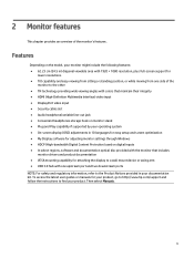
...input ● DisplayPort video input ● Security cable slot ● Audio headphone/variable line-out jack ● Convenient headphones storage hook on monitor stand ● Plug and Play capability if supported by your operating system ● On-screen display (OSD) adjustments in 10 languages for easy...with one upstream port and two downstream ports NOTE: For safety and regulatory information, refer to find your product, go to http://www.hp.com/support and follow the instructions to the Product Notices provided in ) diagonal viewable area with 1920 × 1080 resolution, plus full-...
...input ● DisplayPort video input ● Security cable slot ● Audio headphone/variable line-out jack ● Convenient headphones storage hook on monitor stand ● Plug and Play capability if supported by your operating system ● On-screen display (OSD) adjustments in 10 languages for easy...with one upstream port and two downstream ports NOTE: For safety and regulatory information, refer to find your product, go to http://www.hp.com/support and follow the instructions to the Product Notices provided in ) diagonal viewable area with 1920 × 1080 resolution, plus full-...

Maintenance and Service Guide
Page 8
... Connects the DisplayPort cable from the source device to open the OSD menu, select a menu item from source devices to the monitor. Press to the monitor. Connect the HDMI cables from the OSD, or close the OSD menu. Connects optional powered stereo speakers, headphones, earbuds, a... headset, or a television 4 Connects the USB hub cable from the monitor to a stationary object Connect optional USB devices to turn on the rear of controls and connectors Table 1-1: Front components and their descriptions ...
... Connects the DisplayPort cable from the source device to open the OSD menu, select a menu item from source devices to the monitor. Press to the monitor. Connect the HDMI cables from the OSD, or close the OSD menu. Connects optional powered stereo speakers, headphones, earbuds, a... headset, or a television 4 Connects the USB hub cable from the monitor to a stationary object Connect optional USB devices to turn on the rear of controls and connectors Table 1-1: Front components and their descriptions ...

Maintenance and Service Guide
Page 9
Rear of the monitor showing of the monitor, use this illustration and table. audio cable. Stand components To identify the components on the rear of stand components Table 1-2: Rear components and their descriptions Component 1 Stand release button 2 Headphone storage hook 3 Cable management Function Connects headphone 5
Rear of the monitor showing of the monitor, use this illustration and table. audio cable. Stand components To identify the components on the rear of stand components Table 1-2: Rear components and their descriptions Component 1 Stand release button 2 Headphone storage hook 3 Cable management Function Connects headphone 5
Maintenance and Service Guide
Page 10
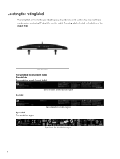
Label location For worldwide models (except India): Barcode label For worldwide models (except India): For India: Barcode label for Worldwide region Spec label For worldwide region Barcode label for India region Spec label for Worldwide region 6 Locating the rating label The rating label on the bottom of the display head. You may need these numbers when contacting HP about the monitor model. The rating label is located on the monitor provides the product number and serial number.
Label location For worldwide models (except India): Barcode label For worldwide models (except India): For India: Barcode label for Worldwide region Spec label For worldwide region Barcode label for India region Spec label for Worldwide region 6 Locating the rating label The rating label on the bottom of the display head. You may need these numbers when contacting HP about the monitor model. The rating label is located on the monitor provides the product number and serial number.
Maintenance and Service Guide
Page 11
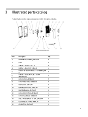
... catalog To identify the monitor major components, use this illustration and table. Mechanical explosion Item Description Qty 1 FRONT BEZEL, OMEN by HP 25, HF 1 2 panel 1 3 SCREW, I, CROSS T, T3*5 ZN 4 4 SCREW, P, CROSS M3*6, ZN-CC 4 5 PCBA, IF/B, W/OSP, LP25Q3-71L/OMEN by HP 25 1 6 SCREW, I, CROSS, M4*6, BLK-Zn, HF (NYLOK)&nbs 4 7 ASSY, CHASSIS, OMEN, HF 1 8 ASSY, STAND HINGE...
... catalog To identify the monitor major components, use this illustration and table. Mechanical explosion Item Description Qty 1 FRONT BEZEL, OMEN by HP 25, HF 1 2 panel 1 3 SCREW, I, CROSS T, T3*5 ZN 4 4 SCREW, P, CROSS M3*6, ZN-CC 4 5 PCBA, IF/B, W/OSP, LP25Q3-71L/OMEN by HP 25 1 6 SCREW, I, CROSS, M4*6, BLK-Zn, HF (NYLOK)&nbs 4 7 ASSY, CHASSIS, OMEN, HF 1 8 ASSY, STAND HINGE...
Maintenance and Service Guide
Page 13
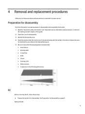
Prepare the area for material flow according to the disassembly layout. 5) Be sure to these steps: ▲ Prepare the monitor for disassembly. 4 Removal and replacement procedures Adherence to have the following equipment and materials: • Press fixture • Working ...Cleaning cloth • ESD protection • Scraper bar in the "Getting started" chapter of monitors. See Preparation for disassembly. 3) Identify the disassembly area. 4) Check the position that the monitors are to be placed along with the number of this information to properly prepare to disassemble and...
Prepare the area for material flow according to the disassembly layout. 5) Be sure to these steps: ▲ Prepare the monitor for disassembly. 4 Removal and replacement procedures Adherence to have the following equipment and materials: • Press fixture • Working ...Cleaning cloth • ESD protection • Scraper bar in the "Getting started" chapter of monitors. See Preparation for disassembly. 3) Identify the disassembly area. 4) Check the position that the monitors are to be placed along with the number of this information to properly prepare to disassemble and...

Maintenance and Service Guide
Page 14
Monitor separate step 2) Unlock 4 screws and pull out the Audio board and Keypad cable then separated the chassis assy form the back cover assy. PCBA and rear cover separate step 3) Unlock 2 screws fixed Keypad and Bucket then the keypad is separated. 10 1) Use hand and a tool to separate back cover assy from monitor as below picture,but pay attention to avoid the LVDS cable and Lightbar cable.
Monitor separate step 2) Unlock 4 screws and pull out the Audio board and Keypad cable then separated the chassis assy form the back cover assy. PCBA and rear cover separate step 3) Unlock 2 screws fixed Keypad and Bucket then the keypad is separated. 10 1) Use hand and a tool to separate back cover assy from monitor as below picture,but pay attention to avoid the LVDS cable and Lightbar cable.
Maintenance and Service Guide
Page 17
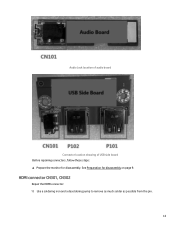
HDMI connector CN301, CN302 Repair the HDMI connector: 1) Use a soldering iron and a desoldering pump to remove as much solder as possible from the pin. 13 Audio Jack location of audio board Connector location showing of USB side board Before repairing connectors, follow these steps: ▲ Prepare the monitor for disassembly on page 9. See Preparation for disassembly.
HDMI connector CN301, CN302 Repair the HDMI connector: 1) Use a soldering iron and a desoldering pump to remove as much solder as possible from the pin. 13 Audio Jack location of audio board Connector location showing of USB side board Before repairing connectors, follow these steps: ▲ Prepare the monitor for disassembly on page 9. See Preparation for disassembly.
Maintenance and Service Guide
Page 21
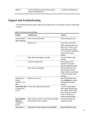
...supported setting. Connect the appropriate video signal cable between computer and USB devices. Be sure that the computer power is off . Monitor is displayed on the keyboard or move the mouse to disable the Power button lockout feature. Video cable is too low. ...USB devices Support and troubleshooting The following table lists possible problems, the possible cause or each problem, and the recommended solutions. The monitor's power saving control is flashing. Power the power button. Change the settings to adjust the brightness scale as needed. indistinct, or...
...supported setting. Connect the appropriate video signal cable between computer and USB devices. Be sure that the computer power is off . Monitor is displayed on the keyboard or move the mouse to disable the Power button lockout feature. Video cable is too low. ...USB devices Support and troubleshooting The following table lists possible problems, the possible cause or each problem, and the recommended solutions. The monitor's power saving control is flashing. Power the power button. Change the settings to adjust the brightness scale as needed. indistinct, or...
Maintenance and Service Guide
Page 22
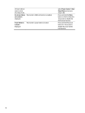
Press and hold the power button for 10 seconds to enter into Sleep mode. select Power Control > AutoSleep Mode and set autosleep to disable the OSD lockout function. Power Button is Locked is Displayed The monitor's power button is enabled. off, but it did not seem to disable the power button lock function. 18 The monitor's OSD lock function is locked. Press and hold the Menu button on the front bezel to 10 seconds to On. On-Screen Menus are Locked is displayed.
Press and hold the power button for 10 seconds to enter into Sleep mode. select Power Control > AutoSleep Mode and set autosleep to disable the OSD lockout function. Power Button is Locked is Displayed The monitor's power button is enabled. off, but it did not seem to disable the power button lock function. 18 The monitor's OSD lock function is locked. Press and hold the Menu button on the front bezel to 10 seconds to On. On-Screen Menus are Locked is displayed.


