

User Guide
Page 5
... display components 7 Connecting the speakers (sold separately 8 Display control panel 9 Identifying remote control buttons 10 Setting up the remote control 11 Mounting a single display on a stand (Sold Separately 12 Installing the HP Frame System (Sold Separately 12 Securing the display ...15 Connecting cables ...15 Connecting multiple displays to one player 24 Connecting multiple displays with Video Over Ethernet (VOE 24 Connecting multiple displays with Tile Mode 26 Mounting the display ...29 Mounting in portrait position 31 Considerations for wall mounting 31 Software...
... display components 7 Connecting the speakers (sold separately 8 Display control panel 9 Identifying remote control buttons 10 Setting up the remote control 11 Mounting a single display on a stand (Sold Separately 12 Installing the HP Frame System (Sold Separately 12 Securing the display ...15 Connecting cables ...15 Connecting multiple displays to one player 24 Connecting multiple displays with Video Over Ethernet (VOE 24 Connecting multiple displays with Tile Mode 26 Mounting the display ...29 Mounting in portrait position 31 Considerations for wall mounting 31 Software...

User Guide
Page 6
... infrared remote control 37 Navigating with the control panel 38 OSD menu selections 39 Power On Delay ...48 Using Key Lock ...48 Setting the backlight level 48 Preventing and fixing ghost images 49 Using Tile Mode ...49 Optimizing analog images ...51 Tuning color ...52 Appendix A Troubleshooting 59 Solving common problems ...59 Using Online Technical Support 62 Product support ...62 Preparing to call technical support 62 Appendix B Technical specifications 63 HP Digital Signage Display ...63 Recognizing preset display resolutions 67 Preset display modes 67...
... infrared remote control 37 Navigating with the control panel 38 OSD menu selections 39 Power On Delay ...48 Using Key Lock ...48 Setting the backlight level 48 Preventing and fixing ghost images 49 Using Tile Mode ...49 Optimizing analog images ...51 Tuning color ...52 Appendix A Troubleshooting 59 Solving common problems ...59 Using Online Technical Support 62 Product support ...62 Preparing to call technical support 62 Appendix B Technical specifications 63 HP Digital Signage Display ...63 Recognizing preset display resolutions 67 Preset display modes 67...

User Guide
Page 7
... or selected control of displays in a video wall ● Tiling for video walls ● Color matching and calibration for all displays in a video wall ● Mercury-free LED backlight ● Ambient light sensor and high brightness for energy savings and good visibility in any light ● Local dimming for enhanced contrast in dark areas of the image ● On-Screen Display (OSD) menu in several languages for ease of setup and screen optimization ● Screen adjustment buttons (Power On/Off, OSD Controls, MENU, and INPUT) on...
... or selected control of displays in a video wall ● Tiling for video walls ● Color matching and calibration for all displays in a video wall ● Mercury-free LED backlight ● Ambient light sensor and high brightness for energy savings and good visibility in any light ● Local dimming for enhanced contrast in dark areas of the image ● On-Screen Display (OSD) menu in several languages for ease of setup and screen optimization ● Screen adjustment buttons (Power On/Off, OSD Controls, MENU, and INPUT) on...

User Guide
Page 8
... Drivers & Downloads, and then follow the on-screen instructions. 2 Chapter 1 Product features To locate updates to the user guide for your product, go to http://www.hp.com/support, and select your documentation kit. ● Security cable provision on rear panel to lock down the display and help prevent theft ● High-bandwidth Digital Content Protection on the DisplayPort input ● Temperature Sensor ● Support VESA compliant mounting interface...
... Drivers & Downloads, and then follow the on-screen instructions. 2 Chapter 1 Product features To locate updates to the user guide for your product, go to http://www.hp.com/support, and select your documentation kit. ● Security cable provision on rear panel to lock down the display and help prevent theft ● High-bandwidth Digital Content Protection on the DisplayPort input ● Temperature Sensor ● Support VESA compliant mounting interface...

User Guide
Page 9
...: • Do not disable the power cord grounding feature. Displays that is easily accessible at www.hp.com/ergo and/or on the documentation disc, if one can replace the equipment, if surge protection fails. If another cord is included with the display. WARNING! For information on the correct power cord set to use only a power source and connection appropriate for computer users, and provides important...
...: • Do not disable the power cord grounding feature. Displays that is easily accessible at www.hp.com/ergo and/or on the documentation disc, if one can replace the equipment, if surge protection fails. If another cord is included with the display. WARNING! For information on the correct power cord set to use only a power source and connection appropriate for computer users, and provides important...

User Guide
Page 10
..., or service provider. ● Use only a power source and connection appropriate for ventilation. Cleaning the display 1. These openings must lay the display face down on the cord. ● Keep the display in the OSD, activate a screen-saver application, periodically cycle between static information and moving images, or turn off the display and unplug the power cord from the back of the unit. 2. If the display is not in use a foam window cleaner...
..., or service provider. ● Use only a power source and connection appropriate for ventilation. Cleaning the display 1. These openings must lay the display face down on the cord. ● Keep the display in the OSD, activate a screen-saver application, periodically cycle between static information and moving images, or turn off the display and unplug the power cord from the back of the unit. 2. If the display is not in use a foam window cleaner...

User Guide
Page 22
... chain (Blue Connector). Serial port for digital video from the previous display in a chain. VGA input connects to external speakers (sold separately). Used by authorized service personnel only. DisplayPort input for control of the display. Infrared input for control of another display to entire device, controller as well as screen. For an audio cable connected to the Line Out on power to support analog video and command data. For a color-calibration device or firmware upgrade. Turns off or on a media player or computer sound card.
... chain (Blue Connector). Serial port for digital video from the previous display in a chain. VGA input connects to external speakers (sold separately). Used by authorized service personnel only. DisplayPort input for control of the display. Infrared input for control of another display to entire device, controller as well as screen. For an audio cable connected to the Line Out on power to support analog video and command data. For a color-calibration device or firmware upgrade. Turns off or on a media player or computer sound card.

User Guide
Page 26
... the VGA cable into the Input (lower) VGA connector of the next display in the chain. (See Connecting multiple displays to one player on the media player/computer. Since the VGA connection does not transmit audio, you will be using analog video, plug the VGA cable into the VGA adaptor on page 24 for more details.) Figure 3-25 DisplayPort Connect the free end of the DisplayPort cable to manage and control the display remotely...
... the VGA cable into the Input (lower) VGA connector of the next display in the chain. (See Connecting multiple displays to one player on the media player/computer. Since the VGA connection does not transmit audio, you will be using analog video, plug the VGA cable into the VGA adaptor on page 24 for more details.) Figure 3-25 DisplayPort Connect the free end of the DisplayPort cable to manage and control the display remotely...

User Guide
Page 34
... to play video that can be set Picture Mode to provide the best IR remote control responsiveness. External IR Sensor NOTE: The number of the External IR Sensor is copy protected with High-bandwidth Digital Content Protection (HDCP), you are connected, the user can issue any OSD command with the IR Remote Control, the display control panel, or for example, turn the displays ON or OFF, set in the wall to...
... to play video that can be set Picture Mode to provide the best IR remote control responsiveness. External IR Sensor NOTE: The number of the External IR Sensor is copy protected with High-bandwidth Digital Content Protection (HDCP), you are connected, the user can issue any OSD command with the IR Remote Control, the display control panel, or for example, turn the displays ON or OFF, set in the wall to...

User Guide
Page 38
... connected displays, associate displays to printer, or from the disc that support this feature. You can attach all displays have been mounted and adjusted. Installing the driver, .INF and .ICM files The display driver firmware and the supporting system files are provided on the wall mount and turn the main power switch ON (|) before mounting, or you can install a USB extension cable in the USB port to the network, and send video from the following HP...
... connected displays, associate displays to printer, or from the disc that support this feature. You can attach all displays have been mounted and adjusted. Installing the driver, .INF and .ICM files The display driver firmware and the supporting system files are provided on the wall mount and turn the main power switch ON (|) before mounting, or you can install a USB extension cable in the USB port to the network, and send video from the following HP...

User Guide
Page 41
... in a video wall. Using the included IR Daisy Chain Cable, connect all the displays simultaneously by selecting an ID of "00". You can easily identify the Using the On-Screen Display menu 35 Using the IR Remote Control or the display control buttons, go to MENU → OPTION 2 → SET MONITOR ID and set the unique ID number (number between 1 and 25) for the new value to apply regardless of the video source. NOTE...
... in a video wall. Using the included IR Daisy Chain Cable, connect all the displays simultaneously by selecting an ID of "00". You can easily identify the Using the On-Screen Display menu 35 Using the IR Remote Control or the display control buttons, go to MENU → OPTION 2 → SET MONITOR ID and set the unique ID number (number between 1 and 25) for the new value to apply regardless of the video source. NOTE...

User Guide
Page 46
... scale makes the image crisper or softer. Off - allows the display to change will show immediately so that matches the input signal. 1280 x 768 pixels 1360 x 768 pixels 1366 x 768 pixels The default setting is Auto. The default setting is 9300. 40 Chapter 4 Operating the display Slightly purplish white. 8000 K - Level 1 Menu Level 2 Menu Contrast Brightness Sharpness Backlight Dynamic Contrast Resolution Color Temperature Level 3 Menu Description Increase or decrease the difference between the light and dark colors. Auto...
... scale makes the image crisper or softer. Off - allows the display to change will show immediately so that matches the input signal. 1280 x 768 pixels 1360 x 768 pixels 1366 x 768 pixels The default setting is Auto. The default setting is 9300. 40 Chapter 4 Operating the display Slightly purplish white. 8000 K - Level 1 Menu Level 2 Menu Contrast Brightness Sharpness Backlight Dynamic Contrast Resolution Color Temperature Level 3 Menu Description Increase or decrease the difference between the light and dark colors. Auto...

User Guide
Page 53
... IR daisy-chain support. Choose yes to upgrade firmware on a USB device plugged into the display. Restores the factory calibration settings. Restore Last Cal. - The IP Address of the network connection handling control data to the display. Yes/No - Restores the last calibration settings. When calibration is complete, the display measures the following : Serial number SW Version (MNT) - MAC Address (NSM) - Enable - The default setting is shown. Using the On-Screen Display menu 47 Enable...
... IR daisy-chain support. Choose yes to upgrade firmware on a USB device plugged into the display. Restores the factory calibration settings. Restore Last Cal. - The IP Address of the network connection handling control data to the display. Yes/No - Restores the last calibration settings. When calibration is complete, the display measures the following : Serial number SW Version (MNT) - MAC Address (NSM) - Enable - The default setting is shown. Using the On-Screen Display menu 47 Enable...

User Guide
Page 58
... or any vertical bars or stripes visible on the frequency setting. 7. It can be connected to the USB port on the keyboard to variations in the Option 1 menu of the OSD. It may be easier to calibrate the displays prior to wall assembly because the colorimeter must be useful to the USB ports. 52 Chapter 4 Operating the display For a permanent wall installation, a rack-mount USB extender facilitates access to calibrate displays that...
... or any vertical bars or stripes visible on the frequency setting. 7. It can be connected to the USB port on the keyboard to variations in the Option 1 menu of the OSD. It may be easier to calibrate the displays prior to wall assembly because the colorimeter must be useful to the USB ports. 52 Chapter 4 Operating the display For a permanent wall installation, a rack-mount USB extender facilitates access to calibrate displays that...

User Guide
Page 65
... the horizontal frequency. See if the power switch is turned on , power indicator is on . Activate a signal source. Adjust the frequency range. To enable the user to display one vertical line. Out of each problem, and the recommended solutions. The vertical frequency or refresh rate is not connected. Power cord is the number of frequency range. Power is green, but the screen appears extremely dark. Problem Possible cause Solution No image is the time to watch the display, the screen image should change multiple...
... the horizontal frequency. See if the power switch is turned on , power indicator is on . Activate a signal source. Adjust the frequency range. To enable the user to display one vertical line. Out of each problem, and the recommended solutions. The vertical frequency or refresh rate is not connected. Power cord is the number of frequency range. Power is green, but the screen appears extremely dark. Problem Possible cause Solution No image is the time to watch the display, the screen image should change multiple...

User Guide
Page 66
... you used a fixed image for Balance, Treble, Bass, and Sound Mode. Sound is turned off. Set the number of adjustment. Check the Speaker and Audio Source settings in the operating system. Equalizer is properly connected. Make sure that matches with the source input signal. OSD Lockout message appears when pressing the Menu button. Horizontal noise appears or the characters look blurred. An after image appears when the display is too dull. Adjust the volume. Signal cable or video card connection is not connected. Key Lock...
... you used a fixed image for Balance, Treble, Bass, and Sound Mode. Sound is turned off. Set the number of adjustment. Check the Speaker and Audio Source settings in the operating system. Equalizer is properly connected. Make sure that matches with the source input signal. OSD Lockout message appears when pressing the Menu button. Horizontal noise appears or the characters look blurred. An after image appears when the display is too dull. Adjust the volume. Signal cable or video card connection is not connected. Key Lock...

User Guide
Page 74
In addition to 20 user modes. User modes are lost when the OSD Factory Reset option is used. High definition video formats Preset 1 2 3 4 5 6 7 8 9 10 Timing Name Pixel Format Horz Freq (kHz) 480i 720x480 15.734 480p 720x480 31.469 720p60 1280x720 ... 1680 x 1050 65.290 29 1920 x 1080 67.5 30 1920 x 1200 74.038 Vertical Frequency (Hz) 60.00 60.000 59.954 60.00 59.950 In addition to these preset modes, the display will store up to frequency and resolution, a user mode includes the Horizontal Position, Vertical Position, Clock, Clock Phase, and Auto Adjustment settings.
In addition to 20 user modes. User modes are lost when the OSD Factory Reset option is used. High definition video formats Preset 1 2 3 4 5 6 7 8 9 10 Timing Name Pixel Format Horz Freq (kHz) 480i 720x480 15.734 480p 720x480 31.469 720p60 1280x720 ... 1680 x 1050 65.290 29 1920 x 1080 67.5 30 1920 x 1200 74.038 Vertical Frequency (Hz) 60.00 60.000 59.954 60.00 59.950 In addition to these preset modes, the display will store up to frequency and resolution, a user mode includes the Horizontal Position, Vertical Position, Clock, Clock Phase, and Auto Adjustment settings.
Video Over Ethernet User Guide
Page 7
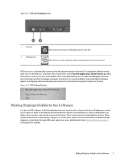
..., each time the player/computer is booted. Making Displays Visible to keep the default setting so players and displays will automatically associate and connect when the player/computer is booted. It is recommended to the Software 3 Enter names and locations at the display, using its on-screen menu (refer to the documentation included with the display), or enter them through VOE when signing...
..., each time the player/computer is booted. Making Displays Visible to keep the default setting so players and displays will automatically associate and connect when the player/computer is booted. It is recommended to the Software 3 Enter names and locations at the display, using its on-screen menu (refer to the documentation included with the display), or enter them through VOE when signing...

Video Over Ethernet User Guide
Page 10
... with any text or numbers meaningful to the user, along with VOE. The Computer Name that may help to populate these fields may be up to view or change the name of the player. To input the Display Name and Display Location information by using VOE, see or change the name of the player. In Windows XP, open the Control Panel, choose System and...
... with any text or numbers meaningful to the user, along with VOE. The Computer Name that may help to populate these fields may be up to view or change the name of the player. To input the Display Name and Display Location information by using VOE, see or change the name of the player. In Windows XP, open the Control Panel, choose System and...

Video Over Ethernet User Guide
Page 38
... any personal firewall software installed on the Player, make sure VOE software is on and properly connected to Update Firmware on the same network can run two firmware programs: ● VOE assignments ● All other . Upgrading firmware is powered-on the Exception List/White List of that the display is low. Thus, players and displays on page 27. 34 Chapter 5 Troubleshooting HP digital signage displays run different versions...
... any personal firewall software installed on the Player, make sure VOE software is on and properly connected to Update Firmware on the same network can run two firmware programs: ● VOE assignments ● All other . Upgrading firmware is powered-on the Exception List/White List of that the display is low. Thus, players and displays on page 27. 34 Chapter 5 Troubleshooting HP digital signage displays run different versions...


