HP G72 Notebook PC - Maintenance and Service Guide
Page 8
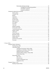
... damage 37 Packaging and transporting guidelines 38 Workstation guidelines 38 Equipment guidelines 39 Component replacement procedures 40 Serial number ...40 Computer feet ...41 Battery ...42 Hard drive ...43 Optical drive ...46 WLAN module ...48 Memory module ...51 RTC battery ...52 Keyboard ...54 Top cover ...57 Speaker assembly ...60 Power button board ...61 TouchPad...
... damage 37 Packaging and transporting guidelines 38 Workstation guidelines 38 Equipment guidelines 39 Component replacement procedures 40 Serial number ...40 Computer feet ...41 Battery ...42 Hard drive ...43 Optical drive ...46 WLAN module ...48 Memory module ...51 RTC battery ...52 Keyboard ...54 Top cover ...57 Speaker assembly ...60 Power button board ...61 TouchPad...
HP G72 Notebook PC - Maintenance and Service Guide
Page 14
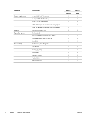
...® 7 Home Premium (32 & 64 bit) Windows 7 Home Basic (32 & 64 bit) Free DOS End-user replaceable parts: AC adapter Battery (system) Hard drive Memory module Optical drive Mini-card devices HP G72 Discrete √ √ √ √ √ HP G72 UMA √ √ √ √ √ √ √ √ √ √ √ √ √ √...
...® 7 Home Premium (32 & 64 bit) Windows 7 Home Basic (32 & 64 bit) Free DOS End-user replaceable parts: AC adapter Battery (system) Hard drive Memory module Optical drive Mini-card devices HP G72 Discrete √ √ √ √ √ HP G72 UMA √ √ √ √ √ √ √ √ √ √ √ √ √ √...
HP G72 Notebook PC - Maintenance and Service Guide
Page 23
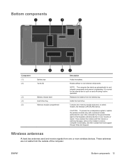
...your country or region. Contains two memory module slots and, on and off during routine operation. If you replace the module and then receive a warning message, remove the module to cool internal components and prevent overheating. These antennas... not visible from the battery bay. Releases the battery from the outside of the computer. Bottom components Component (1) (2) Battery bay Vents (5) (3) Battery release latch (4) Hard drive bay (5) Memory module compartment Description Holds the battery. CAUTION: To prevent an unresponsive system, replace the wireless module only ...
...your country or region. Contains two memory module slots and, on and off during routine operation. If you replace the module and then receive a warning message, remove the module to cool internal components and prevent overheating. These antennas... not visible from the battery bay. Releases the battery from the outside of the computer. Bottom components Component (1) (2) Battery bay Vents (5) (3) Battery release latch (4) Hard drive bay (5) Memory module compartment Description Holds the battery. CAUTION: To prevent an unresponsive system, replace the wireless module only ...
HP G72 Notebook PC - Maintenance and Service Guide
Page 30
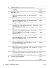
... i5-540M Processor (2.53 GHz, 3 MB total L3 cache, 1066 MHz)- Item (7) (8) (9) (10) Description Spare part number Fan/heat sink assembly (includes replacement thermal material) for models 1.1 and 1.2 only) 613587-001 ● Intel Arrandale i3-380M Processor (2.53 GHz, 3 MB total L3 cache, 1066 MHz)- Dual... (for 634693-001 model 1.2 only) ● Pentium Arrandale P6300 (2.26 GHz 3 MB L3 cache) (for model 1.2 only) 635500-001 RTC battery (includes mounting adhesive) 616501-001 Memory module (1066 MHz, DDR3) ● 1 GB 598859-001 20 Chapter 3 Illustrated parts catalog ENWW
... i5-540M Processor (2.53 GHz, 3 MB total L3 cache, 1066 MHz)- Item (7) (8) (9) (10) Description Spare part number Fan/heat sink assembly (includes replacement thermal material) for models 1.1 and 1.2 only) 613587-001 ● Intel Arrandale i3-380M Processor (2.53 GHz, 3 MB total L3 cache, 1066 MHz)- Dual... (for 634693-001 model 1.2 only) ● Pentium Arrandale P6300 (2.26 GHz 3 MB L3 cache) (for model 1.2 only) 635500-001 RTC battery (includes mounting adhesive) 616501-001 Memory module (1066 MHz, DDR3) ● 1 GB 598859-001 20 Chapter 3 Illustrated parts catalog ENWW
HP G72 Notebook PC - Maintenance and Service Guide
Page 32
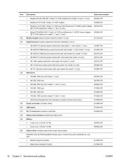
...Adapter (BT3.0+HS ready) (for models 1.1 and 1.2 only) 602992-001 Modem module (select models only) (for model 1.0 only) 510100-001 System board (includes replacement thermal material) for use in: ● HD 5430/1 G discrete system board with card reader 1.1 (for model 1.1 only) 615847-001 ● HD 5430/512 ... connector (includes cable) 616496-001 USB board 616494-001 RJ-11 connector included in Cable Kit 616502-001 Optical drive bracket included with optical drive Battery ● 6-cell Li-lon, 2.20 Ah, 47 Wh 593553-001 ● 6-cell Li-lon, 2.55 Ah, 55 Wh 593554-001 ...
...Adapter (BT3.0+HS ready) (for models 1.1 and 1.2 only) 602992-001 Modem module (select models only) (for model 1.0 only) 510100-001 System board (includes replacement thermal material) for use in: ● HD 5430/1 G discrete system board with card reader 1.1 (for model 1.1 only) 615847-001 ● HD 5430/512 ... connector (includes cable) 616496-001 USB board 616494-001 RJ-11 connector included in Cable Kit 616502-001 Optical drive bracket included with optical drive Battery ● 6-cell Li-lon, 2.20 Ah, 47 Wh 593553-001 ● 6-cell Li-lon, 2.55 Ah, 55 Wh 593554-001 ...
HP G72 Notebook PC - Maintenance and Service Guide
Page 50
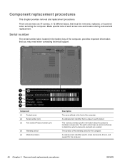
...Product number (p/n) (4) Warranty period (5) Model description Description The name affixed to each screw size and location during removal and replacement. The duration of the computer, provides important information that is unique to the front of each product. An alphanumeric identifier used...are as many as 75 screws, in the battery bay of the warranty period for the computer. 40 Chapter 4 Removal and replacement procedures ENWW Component replacement procedures This chapter provides removal and replacement procedures. This number provides specific information about the...
...Product number (p/n) (4) Warranty period (5) Model description Description The name affixed to each screw size and location during removal and replacement. The duration of the computer, provides important information that is unique to the front of each product. An alphanumeric identifier used...are as many as 75 screws, in the battery bay of the warranty period for the computer. 40 Chapter 4 Removal and replacement procedures ENWW Component replacement procedures This chapter provides removal and replacement procedures. This number provides specific information about the...
HP G72 Notebook PC - Maintenance and Service Guide
Page 52
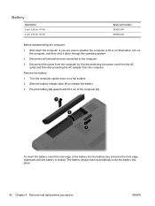
... latch (1) to the computer. 3. The battery release latch automatically locks the battery into the battery bay and pivot the front edge downward until the battery is off or in Hibernation, turn on a flat surface. 2. Shut down through the operating system. 2. If you are unsure whether ... the computer upside down on the computer, and then shut it out of the battery into place. 42 Chapter 4 Removal and replacement procedures ENWW To insert the battery, insert the rear edge of the computer (3). Remove the battery: 1. Battery Description 6 cell, 2.20 Ah, 47 Wh 6 cell, 2.55 Ah, 55 ...
... latch (1) to the computer. 3. The battery release latch automatically locks the battery into the battery bay and pivot the front edge downward until the battery is off or in Hibernation, turn on a flat surface. 2. Shut down through the operating system. 2. If you are unsure whether ... the computer upside down on the computer, and then shut it out of the battery into place. 42 Chapter 4 Removal and replacement procedures ENWW To insert the battery, insert the rear edge of the computer (3). Remove the battery: 1. Battery Description 6 cell, 2.20 Ah, 47 Wh 6 cell, 2.55 Ah, 55 ...

HP G72 Notebook PC - Maintenance and Service Guide
Page 53
... connector, as well as the hard drive bracket screws, are unsure whether the computer is off or in the Hard Drive Hardware Kit. ENWW Component replacement procedures 43 Loosen the two Phillips PM2.5×6.0 captive screws (1) that secure the hard drive cover to the computer. 3. Disconnect all external devices connected to... part number 603787-001 603785-001 615085-001 622643-001 615084-001 615083-001 615082-001 615086-001 Before removing the hard drive: 1. Remove the battery (see Battery on the computer, and then shut it down the computer.
... connector, as well as the hard drive bracket screws, are unsure whether the computer is off or in the Hard Drive Hardware Kit. ENWW Component replacement procedures 43 Loosen the two Phillips PM2.5×6.0 captive screws (1) that secure the hard drive cover to the computer. 3. Disconnect all external devices connected to... part number 603787-001 603785-001 615085-001 622643-001 615084-001 615083-001 615082-001 615086-001 Before removing the hard drive: 1. Remove the battery (see Battery on the computer, and then shut it down the computer.
HP G72 Notebook PC - Maintenance and Service Guide
Page 56
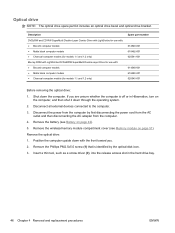
...3. Remove the optical drive: 1. Disconnect all external devices connected to the computer. 3. Remove the wireless/memory module compartment cover (see Battery on page 51). Description DVD±RW and CD-RW SuperMulti Double-Layer Combo Drive with LightScribe for use with: ● Biscotti .... 2. Remove the Phillips PM2.5x5.0 screw (1) that is off or in the hard drive bay. 46 Chapter 4 Removal and replacement procedures ENWW Remove the battery (see Memory module on page 42). 5. Shut down through the operating system. 2. Optical drive NOTE: The optical drive spare part ...
...3. Remove the optical drive: 1. Disconnect all external devices connected to the computer. 3. Remove the wireless/memory module compartment cover (see Battery on page 51). Description DVD±RW and CD-RW SuperMulti Double-Layer Combo Drive with LightScribe for use with: ● Biscotti .... 2. Remove the Phillips PM2.5x5.0 screw (1) that is off or in the hard drive bay. 46 Chapter 4 Removal and replacement procedures ENWW Remove the battery (see Memory module on page 42). 5. Shut down through the operating system. 2. Optical drive NOTE: The optical drive spare part ...
HP G72 Notebook PC - Maintenance and Service Guide
Page 58
... cover. 3. Disconnect all external devices connected to the computer. 3. Lift the back side of the memory module cover (2). 48 Chapter 4 Removal and replacement procedures ENWW Remove the battery (see Battery on the computer, and then shut it down with the front toward you are unsure whether the computer is off or in Hibernation...
... cover. 3. Disconnect all external devices connected to the computer. 3. Lift the back side of the memory module cover (2). 48 Chapter 4 Removal and replacement procedures ENWW Remove the battery (see Battery on the computer, and then shut it down with the front toward you are unsure whether the computer is off or in Hibernation...
HP G72 Notebook PC - Maintenance and Service Guide
Page 61
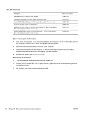
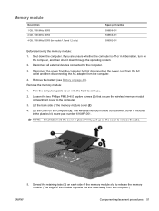
...on each side of the memory module slot to release the tabs. 5. Disconnect all external devices connected to the computer. 3. Remove the battery (see Battery on the cover to release the memory module. (The edge of the memory module cover (2) 4. Lift the back side of the module... the computer by first disconnecting the power cord from the AC outlet and then disconnecting the AC adapter from the computer.) ENWW Component replacement procedures 51 Loosen the two Phillips PM2.5×6.0 captive screws (1) that secure the wireless/memory module compartment cover to the computer. 3....
...on each side of the memory module slot to release the tabs. 5. Disconnect all external devices connected to the computer. 3. Remove the battery (see Battery on the cover to release the memory module. (The edge of the memory module cover (2) 4. Lift the back side of the module... the computer by first disconnecting the power cord from the AC outlet and then disconnecting the AC adapter from the computer.) ENWW Component replacement procedures 51 Loosen the two Phillips PM2.5×6.0 captive screws (1) that secure the wireless/memory module compartment cover to the computer. 3....
HP G72 Notebook PC - Maintenance and Service Guide
Page 62
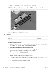
...devices connected to the computer. 3. Disconnect the power from the computer by pulling it down through the operating system. 2. Remove the RTC battery: 1. NOTE: Memory modules are designed with the front toward you are unsure whether the computer is off or in Hibernation, turn on.... Turn the computer upside down the computer. Remove the battery (see Battery on the computer, and then shut it away from the computer. 4. Lift the back side of the memory module cover (2) 52 Chapter 4 Removal and replacement procedures ENWW Remove the module (2) by first disconnecting the ...
...devices connected to the computer. 3. Disconnect the power from the computer by pulling it down through the operating system. 2. Remove the RTC battery: 1. NOTE: Memory modules are designed with the front toward you are unsure whether the computer is off or in Hibernation, turn on.... Turn the computer upside down the computer. Remove the battery (see Battery on the computer, and then shut it away from the computer. 4. Lift the back side of the memory module cover (2) 52 Chapter 4 Removal and replacement procedures ENWW Remove the module (2) by first disconnecting the ...
HP G72 Notebook PC - Maintenance and Service Guide
Page 63
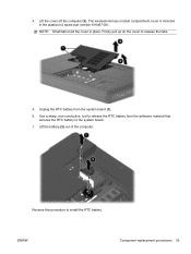
Firmly pull up on the cover to install the RTC battery. ENWW Component replacement procedures 53 The wireless/memory module compartment cover is included in place. Use a sharp, non-conductive, tool to the system board.. 7. Lift the cover off the computer (3). Unplug the RTC battery from the adhesive material that secures the RTC battery to release the RTC battery from the system board (1). 6. Reverse this procedure to release the tabs. 5. 4. NOTE: Small tabs hold the cover in the plastics kit, spare part number 616497-001. Lift the battery (2) out of the computer.
Firmly pull up on the cover to install the RTC battery. ENWW Component replacement procedures 53 The wireless/memory module compartment cover is included in place. Use a sharp, non-conductive, tool to the system board.. 7. Lift the cover off the computer (3). Unplug the RTC battery from the adhesive material that secures the RTC battery to release the RTC battery from the system board (1). 6. Reverse this procedure to release the tabs. 5. 4. NOTE: Small tabs hold the cover in the plastics kit, spare part number 616497-001. Lift the battery (2) out of the computer.
HP G72 Notebook PC - Maintenance and Service Guide
Page 64
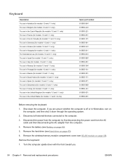
... Hard drive on page 48). Turn the computer upside down through the operating system. 2. Disconnect all external devices connected to the computer. 3. Remove the battery (see Battery on the computer, and then shut it down with the front toward you are unsure whether the computer is off or in the United States...-131 615850-251 615850-171 615850-071 615850-BG1 615850-141 615850-031 615850-001 Before removing the keyboard: 1. If you . 54 Chapter 4 Removal and replacement procedures ENWW Shut down the computer.
... Hard drive on page 48). Turn the computer upside down through the operating system. 2. Disconnect all external devices connected to the computer. 3. Remove the battery (see Battery on the computer, and then shut it down with the front toward you are unsure whether the computer is off or in the United States...-131 615850-251 615850-171 615850-071 615850-BG1 615850-141 615850-031 615850-001 Before removing the keyboard: 1. If you . 54 Chapter 4 Removal and replacement procedures ENWW Shut down the computer.
HP G72 Notebook PC - Maintenance and Service Guide
Page 67
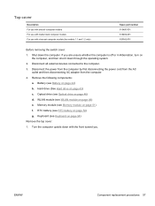
Disconnect all external devices connected to the computer. 3. WLAN module (see Keyboard on page 48) e. ENWW Component replacement procedures 57 Top cover Description For use with biscotti computer models For use with matte black computer models For use with the ... cover: 1. Remove the following components: a. Optical drive (see Memory module on page 46) d. Memory module (see Optical drive on page 51) f. RTC battery (see Battery on page 52) g. Battery (see RTC battery on page 42) b. Hard drive (See Hard drive on the computer, and then shut it down the computer.
Disconnect all external devices connected to the computer. 3. WLAN module (see Keyboard on page 48) e. ENWW Component replacement procedures 57 Top cover Description For use with biscotti computer models For use with matte black computer models For use with the ... cover: 1. Remove the following components: a. Optical drive (see Memory module on page 46) d. Memory module (see Optical drive on page 51) f. RTC battery (see Battery on page 52) g. Battery (see RTC battery on page 42) b. Hard drive (See Hard drive on the computer, and then shut it down the computer.
HP G72 Notebook PC - Maintenance and Service Guide
Page 68
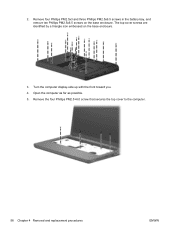
Remove four Phillips PM2.5x3 and three Phillips PM2.5x6.5 screws in the battery bay, and remove ten Phillips PM2.5x6.5 screws on the base enclosure. 3. Turn the computer display-side up with the front toward you. 4. The top cover screws are identified by a triangle icon embossed on the base enclosure. Remove the four Phillips PM2.5×6.0 screw that secures the top cover to the computer. 58 Chapter 4 Removal and replacement procedures ENWW Open the computer as far as possible. 5. 2.
Remove four Phillips PM2.5x3 and three Phillips PM2.5x6.5 screws in the battery bay, and remove ten Phillips PM2.5x6.5 screws on the base enclosure. 3. Turn the computer display-side up with the front toward you. 4. The top cover screws are identified by a triangle icon embossed on the base enclosure. Remove the four Phillips PM2.5×6.0 screw that secures the top cover to the computer. 58 Chapter 4 Removal and replacement procedures ENWW Open the computer as far as possible. 5. 2.
HP G72 Notebook PC - Maintenance and Service Guide
Page 70
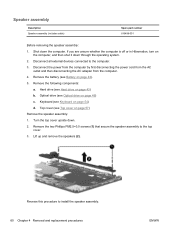
... (includes cable) Spare part number 616498-001 Before removing the speaker assembly: 1. Shut down . 2. Remove the battery (see Optical drive on the computer, and then shut it down through the operating system. 2. Optical drive (see Battery on page 54) d. Remove the two Phillips PM2.5×3.0 screws (1) that secure the speaker assembly to... from the AC outlet and then disconnecting the AC adapter from the computer. 4. Reverse this procedure to install the speaker assembly. 60 Chapter 4 Removal and replacement procedures ENWW
... (includes cable) Spare part number 616498-001 Before removing the speaker assembly: 1. Shut down . 2. Remove the battery (see Optical drive on the computer, and then shut it down through the operating system. 2. Optical drive (see Battery on page 54) d. Remove the two Phillips PM2.5×3.0 screws (1) that secure the speaker assembly to... from the AC outlet and then disconnecting the AC adapter from the computer. 4. Reverse this procedure to install the speaker assembly. 60 Chapter 4 Removal and replacement procedures ENWW
HP G72 Notebook PC - Maintenance and Service Guide
Page 71
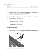
...Spare part number 616495-001 Before removing the power button board: 1. Disconnect all external devices connected to the top cover. 3. Remove the battery (see Top cover on page 42). 5. Remove the Phillips PM2.0×3.0 screw (1) that secures the power button board to the computer.... the AC adapter from the computer. 4. Top cover (see Battery on page 57) Remove the power button board: 1. Optical drive (see Keyboard on page 46) c. Keyboard (see Optical drive on page 54) d. ENWW Component replacement procedures 61 Lift up and remove the power button board (2). ...
...Spare part number 616495-001 Before removing the power button board: 1. Disconnect all external devices connected to the top cover. 3. Remove the battery (see Top cover on page 42). 5. Remove the Phillips PM2.0×3.0 screw (1) that secures the power button board to the computer.... the AC adapter from the computer. 4. Top cover (see Battery on page 57) Remove the power button board: 1. Optical drive (see Keyboard on page 46) c. Keyboard (see Optical drive on page 54) d. ENWW Component replacement procedures 61 Lift up and remove the power button board (2). ...

Notebook PC User Guide - Windows 7
Page 64
... work . To reduce potential safety issues, use only the battery provided with the computer, a replacement battery provided by HP, or a compatible battery purchased from external power. To run Battery Check: 1. Battery Check examines the battery and its cells to the computer, and other factors. If the computer contains a charged battery and is running on the status of the Total...
... work . To reduce potential safety issues, use only the battery provided with the computer, a replacement battery provided by HP, or a compatible battery purchased from external power. To run Battery Check: 1. Battery Check examines the battery and its cells to the computer, and other factors. If the computer contains a charged battery and is running on the status of the Total...
Notebook PC User Guide - Windows 7
Page 72
... burns, do not disassemble, crush, or puncture; If the battery is not charging properly, or when the battery storage capacity has reached a weak condition. Replacing the battery Computer battery life varies, depending on power management settings, programs running on the computer, display brightness, external devices connected to the HP Web site for more information about ordering a replacement battery.
... burns, do not disassemble, crush, or puncture; If the battery is not charging properly, or when the battery storage capacity has reached a weak condition. Replacing the battery Computer battery life varies, depending on power management settings, programs running on the computer, display brightness, external devices connected to the HP Web site for more information about ordering a replacement battery.


