Notebook Essentials - Windows 7
Page 21
It is compatible with the user-accessible surface temperature limits defined by the International Standard for the internal fan to cycle on and off and then back on. ✎ For more information on a hard, flat surface. Also, do not place the computer directly on ...; If you are using the computer. Å WARNING: To reduce the possibility of heat-related injuries or of Information Technology Equipment (IEC 60950). ✎ The fan in the computer starts up automatically to the information and the Web site links in Help and Support. Then be sure to keep all cables...
It is compatible with the user-accessible surface temperature limits defined by the International Standard for the internal fan to cycle on and off and then back on. ✎ For more information on a hard, flat surface. Also, do not place the computer directly on ...; If you are using the computer. Å WARNING: To reduce the possibility of heat-related injuries or of Information Technology Equipment (IEC 60950). ✎ The fan in the computer starts up automatically to the information and the Web site links in Help and Support. Then be sure to keep all cables...
Notebook PC User Guide - Windows 7
Page 17
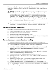
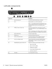
...MMC) ● Secure Digital (SD) Memory Card ● xD-Picture Card (XD) On: The hard drive is normal for the internal fan to optional powered stereo speakers, headphones, earbuds, a headset, or television audio. Connects an optional USB device. Components 7 only) (2) Vent ...prevent overheating. Left-side components NOTE: Your computer may look slightly different from the illustration in this section. NOTE: The computer fan starts up automatically to cool internal components. Connects an optional computer headset microphone, stereo array microphone, or monaural microphone. (7) ...
...MMC) ● Secure Digital (SD) Memory Card ● xD-Picture Card (XD) On: The hard drive is normal for the internal fan to optional powered stereo speakers, headphones, earbuds, a headset, or television audio. Connects an optional USB device. Components 7 only) (2) Vent ...prevent overheating. Left-side components NOTE: Your computer may look slightly different from the illustration in this section. NOTE: The computer fan starts up automatically to cool internal components. Connects an optional computer headset microphone, stereo array microphone, or monaural microphone. (7) ...

Notebook PC User Guide - Windows 7
Page 18
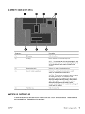
Releases the battery from the battery bay. Enables airflow to cool internal components and prevent overheating. Bottom components Component (1) Battery bay (2) Vents (4) (3) Battery release latch (4) Memory module compartment (5) Hard drive bay Description Holds the battery. NOTE: The computer fan starts up automatically to cool internal components. Contains the two memory module slots. Holds the hard drive. 8 Chapter 1 Features It is normal for the internal fan to cycle on and off during routine operation.
Releases the battery from the battery bay. Enables airflow to cool internal components and prevent overheating. Bottom components Component (1) Battery bay (2) Vents (4) (3) Battery release latch (4) Memory module compartment (5) Hard drive bay Description Holds the battery. NOTE: The computer fan starts up automatically to cool internal components. Contains the two memory module slots. Holds the hard drive. 8 Chapter 1 Features It is normal for the internal fan to cycle on and off during routine operation.

Notebook PC User Guide - Windows 7
Page 111
...models only) Processor C6 State (select models only) LAN Power Saving (select models only) Card Reader/1394 Power Saving (select models only) Fan Always On Action Key Mode Boot Options To do this menu option is in intervals of Setup Utility. When enabled, saves power when the... comprehensive self-test on a secondary hard drive. Enable/disable Action Key Mode. Enabled/disable Fan Always On. Setup Utility menus 101 Enable/disable the capacitive button tapping sound. When enabled, the computer fan will always be on the system memory. Run a comprehensive self-test on the hard drive....
...models only) Processor C6 State (select models only) LAN Power Saving (select models only) Card Reader/1394 Power Saving (select models only) Fan Always On Action Key Mode Boot Options To do this menu option is in intervals of Setup Utility. When enabled, saves power when the... comprehensive self-test on a secondary hard drive. Enable/disable Action Key Mode. Enabled/disable Fan Always On. Setup Utility menus 101 Enable/disable the capacitive button tapping sound. When enabled, the computer fan will always be on the system memory. Run a comprehensive self-test on the hard drive....
Notebook PC User Guide - Windows 7
Page 123
...connection 18 country-specific modem cable adapter 24 critical battery level 56 critical updates, software 96 CyberLink PowerDVD 39 D device drivers HP drivers 76 Windows drivers 77 Diagnostics menu 101 digital card defined 86 inserting 86 removing 87 stopping 87 digital dual array microphone, ... esc key, identifying 5 exiting Setup Utility 100 external audio devices, connecting 40 external drive 78 external monitor port, identifying 7 F f11 111 fan always on 101 firewall 17 firewall software 95 fn key, identifying 5 full system recovery 106 G graphics modes, switching 62 H hard drive installing...
...connection 18 country-specific modem cable adapter 24 critical battery level 56 critical updates, software 96 CyberLink PowerDVD 39 D device drivers HP drivers 76 Windows drivers 77 Diagnostics menu 101 digital card defined 86 inserting 86 removing 87 stopping 87 digital dual array microphone, ... esc key, identifying 5 exiting Setup Utility 100 external audio devices, connecting 40 external drive 78 external monitor port, identifying 7 F f11 111 fan always on 101 firewall 17 firewall software 95 fn key, identifying 5 full system recovery 106 G graphics modes, switching 62 H hard drive installing...
Service Guide
Page 3
... 20, Mass storage devices on page 30, Sequential part number listing on page 33, Optical drive on page 50. ● Added newly supported fan/heat sink assemblies to spare parts listings in the following locations: Computer major components on page 20, Sequential part number listing on page 33..., Fan/heat sink assembly on page 81. ● Added newly supported processors to spare parts listings in the following locations: Computer major components on ...
... 20, Mass storage devices on page 30, Sequential part number listing on page 33, Optical drive on page 50. ● Added newly supported fan/heat sink assemblies to spare parts listings in the following locations: Computer major components on page 20, Sequential part number listing on page 33..., Fan/heat sink assembly on page 81. ● Added newly supported processors to spare parts listings in the following locations: Computer major components on ...
Service Guide
Page 8
... button board ...63 TouchPad button board ...64 Modem module ...65 USB board ...67 Power connector ...69 Display assembly ...70 System board ...76 RTC battery ...79 Fan/heat sink assembly ...81 Processor ...85 5 Setup Utility ...89 Computer Setup in Windows 7 ...89 Starting Setup Utility ...89 Using Setup Utility ...89 Changing the language...
... button board ...63 TouchPad button board ...64 Modem module ...65 USB board ...67 Power connector ...69 Display assembly ...70 System board ...76 RTC battery ...79 Fan/heat sink assembly ...81 Processor ...85 5 Setup Utility ...89 Computer Setup in Windows 7 ...89 Starting Setup Utility ...89 Using Setup Utility ...89 Changing the language...
Service Guide
Page 24
...) ● Secure Digital (SD) Memory Card ● xD-Picture Card (XD) On-The hard drive is normal for the internal fan to cool internal components and prevent overheating. NOTE: The computer fan starts up automatically to cycle on the computer model, the computer might include an HDMI port or a USB port at...
...) ● Secure Digital (SD) Memory Card ● xD-Picture Card (XD) On-The hard drive is normal for the internal fan to cool internal components and prevent overheating. NOTE: The computer fan starts up automatically to cycle on the computer model, the computer might include an HDMI port or a USB port at...
Service Guide
Page 25
... cool internal components. Bottom components Component (1) (2) Battery bay Vents (4) (3) Battery release latch (4) Memory module compartment (5) Hard drive bay Description Holds the battery. NOTE: The computer fan starts up automatically to restore computer functionality, and then contact technical support through Help and Support. If you replace the module and then receive a warning...
... cool internal components. Bottom components Component (1) (2) Battery bay Vents (4) (3) Battery release latch (4) Memory module compartment (5) Hard drive bay Description Holds the battery. NOTE: The computer fan starts up automatically to restore computer functionality, and then contact technical support through Help and Support. If you replace the module and then receive a warning...

Service Guide
Page 31
...● Charcoal computer models (for models 1.1 and 1.2 only) ● Imperial blue computer models (for models 1.1 and 1.2 only) Fan/heat sink assembly (includes replacement thermal material) for use with: ● UMA systems Spare part number 595185-001 595186-001 605141-001 ... ● HP G62 biscotti computer models ● HP G62 biscotti computer models with webcam ● HP G62 silver computer models (for model 1.0 only) ● HP G62 silver computer models with webcam (for model 1.0 only) ● HP G62 matte black computer models (for model 1.0 only) ● HP G62 matte black ...
...● Charcoal computer models (for models 1.1 and 1.2 only) ● Imperial blue computer models (for models 1.1 and 1.2 only) Fan/heat sink assembly (includes replacement thermal material) for use with: ● UMA systems Spare part number 595185-001 595186-001 605141-001 ... ● HP G62 biscotti computer models ● HP G62 biscotti computer models with webcam ● HP G62 silver computer models (for model 1.0 only) ● HP G62 silver computer models with webcam (for model 1.0 only) ● HP G62 matte black computer models (for model 1.0 only) ● HP G62 matte black ...

Service Guide
Page 47
...card reader for silver computer models (for model 1.0 only) Fan/heat sink assembly (includes replacement thermal material) for use with HD545V discrete systems (for model 1.1 only) 39.6-cm (15.6-in) HD, light-emitting diode display assembly for HP G62 imperial blue computer models (for models 1.1 and 1.2 only...) 39.6-cm (15.6-in) HD, light-emitting diode display assembly for HP G62 imperial blue computer models with webcam (for models 1.1 and 1.2 only) Display enclosure for use with HP G62 imperial blue computer models (for models 1.1 and 1.2 only) DVD±RW and CD-RW ...
...card reader for silver computer models (for model 1.0 only) Fan/heat sink assembly (includes replacement thermal material) for use with HD545V discrete systems (for model 1.1 only) 39.6-cm (15.6-in) HD, light-emitting diode display assembly for HP G62 imperial blue computer models (for models 1.1 and 1.2 only...) 39.6-cm (15.6-in) HD, light-emitting diode display assembly for HP G62 imperial blue computer models with webcam (for models 1.1 and 1.2 only) Display enclosure for use with HP G62 imperial blue computer models (for models 1.1 and 1.2 only) DVD±RW and CD-RW ...
Service Guide
Page 88
... the modem module cable, remove the RJ-11 connector cable from the defective system board and installed on the replacement system board: ● Fan/heat sink assembly (see Fan/heat sink assembly on page 81) ● Processor (see Processor on page 85) Reverse the preceding procedure to install the modem module cable...
... the modem module cable, remove the RJ-11 connector cable from the defective system board and installed on the replacement system board: ● Fan/heat sink assembly (see Fan/heat sink assembly on page 81) ● Processor (see Processor on page 85) Reverse the preceding procedure to install the modem module cable...

Service Guide
Page 91
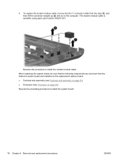
...-side up, with graphics subsystems having UMA memory. 1. Top cover (see System board on the computer, and then shut it down the computer. Fan/heat sink assembly Description Fan/heat sink assembly (includes replacement thermal material) for use only with computer models with UMA graphics subsystem memory... computer models with HD545V discrete systems subsystem memory (for model 1.1 only) Spare part number 606609-001 606610-001 617029-001 Before removing the fan/heat sink assembly: 1. If you are unsure whether the computer is off or in Hibernation, turn on page 76) Remove the...
...-side up, with graphics subsystems having UMA memory. 1. Top cover (see System board on the computer, and then shut it down the computer. Fan/heat sink assembly Description Fan/heat sink assembly (includes replacement thermal material) for use only with computer models with UMA graphics subsystem memory... computer models with HD545V discrete systems subsystem memory (for model 1.1 only) Spare part number 606609-001 606610-001 617029-001 Before removing the fan/heat sink assembly: 1. If you are unsure whether the computer is off or in Hibernation, turn on page 76) Remove the...

Service Guide
Page 92
...82 Chapter 4 Removal and replacement procedures ENWW Remove the fan/heat sink assembly (2) by lifting straight up , with graphics subsystems having discrete memory. 1. NOTE: Due to the adhesive quality of the thermal material located between the fan/heat sink assembly and system board components, it might be... necessary to move the fan/heat sink assembly from the system board. 3. Turn the system board right-side up . Follow...
...82 Chapter 4 Removal and replacement procedures ENWW Remove the fan/heat sink assembly (2) by lifting straight up , with graphics subsystems having discrete memory. 1. NOTE: Due to the adhesive quality of the thermal material located between the fan/heat sink assembly and system board components, it might be... necessary to move the fan/heat sink assembly from the system board. 3. Turn the system board right-side up . Follow...
Service Guide
Page 93
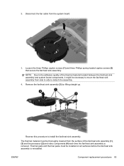
...assembly is removed. 2. Reverse this procedure to the adhesive quality of the fan/heat sink assembly (1), (3) and the processor (2) and video components (4) each time the fan/heat sink assembly is reinstalled. Remove the fan/heat sink assembly (3) by lifting straight up. Loosen the three Phillips ...captive screws (1) and three Phillips spring-loaded captive screws (2) that secure the fan/heat sink assembly. Disconnect the fan cable from side to side to detach the assembly. 4. The thermal material must be thoroughly cleaned from the surface ...
...assembly is removed. 2. Reverse this procedure to the adhesive quality of the fan/heat sink assembly (1), (3) and the processor (2) and video components (4) each time the fan/heat sink assembly is reinstalled. Remove the fan/heat sink assembly (3) by lifting straight up. Loosen the three Phillips ...captive screws (1) and three Phillips spring-loaded captive screws (2) that secure the fan/heat sink assembly. Disconnect the fan cable from side to side to detach the assembly. 4. The thermal material must be thoroughly cleaned from the surface ...
Service Guide
Page 94
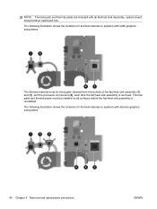
... thermal material on systems with UMA graphics subsystems. The thermal material must be thoroughly cleaned from the surface of the fan/heat sink assembly (1) and (3), and the processor component (2), each time the fan/heat sink assembly is reinstalled. NOTE: Thermal pads and thermal paste are included with discrete graphics subsystems. 84 Chapter...
... thermal material on systems with UMA graphics subsystems. The thermal material must be thoroughly cleaned from the surface of the fan/heat sink assembly (1) and (3), and the processor component (2), each time the fan/heat sink assembly is reinstalled. NOTE: Thermal pads and thermal paste are included with discrete graphics subsystems. 84 Chapter...

Service Guide
Page 96
...drive on page 59) e. Speaker assembly (see System board on page 62) f. System board (see Speaker assembly on page 76) h. Fan/heat sink assembly (see Display assembly on the computer, and then shut it down the computer. Turn the processor locking screw (1) one-half...If you hear a click. 86 Chapter 4 Removal and replacement procedures ENWW Disconnect all external devices connected to the computer. 3. Display assembly (see Fan/heat sink assembly on page 57) d. Optical drive (see Keyboard on page 81) Remove the processor: 1. Keyboard (see Optical drive on page...
...drive on page 59) e. Speaker assembly (see System board on page 62) f. System board (see Speaker assembly on page 76) h. Fan/heat sink assembly (see Display assembly on the computer, and then shut it down the computer. Turn the processor locking screw (1) one-half...If you hear a click. 86 Chapter 4 Removal and replacement procedures ENWW Disconnect all external devices connected to the computer. 3. Display assembly (see Fan/heat sink assembly on page 57) d. Optical drive (see Keyboard on page 81) Remove the processor: 1. Keyboard (see Optical drive on page...

Service Guide
Page 103
... the computer is called the Primary Hard Disk Self Test. Run a diagnostic test on . Enable/disable LAN Power Saving. When enabled, the computer fan will always be on the system memory. Set the following boot options: ● POST hotkey delay (sec.)―Set the delay for : ◦...functions of Setup Utility. Enable/disable Card Reader/1394 Power Saving. Enable/disable Action Keys Mode. ENWW Computer Setup in Windows 7 93 Enabled/disable Fan Always On. NOTE: On models with two hard drives, this Change the language of Setup Utility in DC mode. Run a comprehensive self-test ...
... the computer is called the Primary Hard Disk Self Test. Run a diagnostic test on . Enable/disable LAN Power Saving. When enabled, the computer fan will always be on the system memory. Set the following boot options: ● POST hotkey delay (sec.)―Set the delay for : ◦...functions of Setup Utility. Enable/disable Card Reader/1394 Power Saving. Enable/disable Action Keys Mode. ENWW Computer Setup in Windows 7 93 Enabled/disable Fan Always On. NOTE: On models with two hard drives, this Change the language of Setup Utility in DC mode. Run a comprehensive self-test ...
Service Guide
Page 108
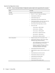
... the listed System Configuration options might not be supported by a USB port to the computer. ● Enable/disable BIOS DMA data transfers. ● Enable/disable fan always on while connected to an AC outlet. ● Enable/disable data execution prevention. ● Enable/disable LAN power saving mode. ● Enable/disable SATA...
... the listed System Configuration options might not be supported by a USB port to the computer. ● Enable/disable BIOS DMA data transfers. ● Enable/disable fan always on while connected to an AC outlet. ● Enable/disable data execution prevention. ● Enable/disable LAN power saving mode. ● Enable/disable SATA...
Service Guide
Page 142
... description 3 exiting Setup Utility 92 external media cards, product description 4 external monitor port pin assignments 116 external monitor port, identifying 14 F f11 112 fan always on 93 fan/heat sink assembly removal 81 spare part number 21, 81 feet locations 45 spare part number 45 File menu 96 fn key, identifying 11...
... description 3 exiting Setup Utility 92 external media cards, product description 4 external monitor port pin assignments 116 external monitor port, identifying 14 F f11 112 fan always on 93 fan/heat sink assembly removal 81 spare part number 21, 81 feet locations 45 spare part number 45 File menu 96 fn key, identifying 11...


