Service Guide
Page 5
... cover 4-30 TouchPad on/off button board and board bracket 4-32 Audio board 4-34 Bluetooth module 4-35 Speakers 4-36 USB board 4-37 System board 4-38 Fan/heat sink assembly 4-41 Processor 4-44 Power connector cable 4-46 5 Setup Utility Starting the Setup Utility 5-1 Changing the language of the Setup Utility 5-1 Navigating and...
... cover 4-30 TouchPad on/off button board and board bracket 4-32 Audio board 4-34 Bluetooth module 4-35 Speakers 4-36 USB board 4-37 System board 4-38 Fan/heat sink assembly 4-41 Processor 4-44 Power connector cable 4-46 5 Setup Utility Starting the Setup Utility 5-1 Changing the language of the Setup Utility 5-1 Navigating and...
Service Guide
Page 18
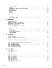
Blinking: The hard drive or optical drive is turned off or in the computer are fully charged. It is normal for the internal fan to cycle on . ■ Blinking: The computer is in the Sleep state. ■ Off: The computer is off when all batteries in Hibernation...the computer is not plugged into an external power source, the light is being accessed. Function Enable airflow to cool internal components. ✎ The computer fan starts up automatically to optional powered stereo speakers, headphones, ear buds, a headset, or television audio. Front components Item Component 1 Power light 2 ...
Blinking: The hard drive or optical drive is turned off or in the computer are fully charged. It is normal for the internal fan to cycle on . ■ Blinking: The computer is in the Sleep state. ■ Off: The computer is off when all batteries in Hibernation...the computer is not plugged into an external power source, the light is being accessed. Function Enable airflow to cool internal components. ✎ The computer fan starts up automatically to optional powered stereo speakers, headphones, ear buds, a headset, or television audio. Front components Item Component 1 Power light 2 ...
Service Guide
Page 20
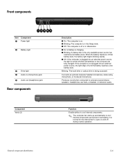
...; To prevent an unresponsive system, replace the wireless module with only a wireless module authorized for the internal fan to cool internal components and prevent overheating. Enable airflow to cool internal components. ✎ The computer fan starts up automatically to cycle on and off during routine operation. If you replace the module and...
...; To prevent an unresponsive system, replace the wireless module with only a wireless module authorized for the internal fan to cool internal components and prevent overheating. Enable airflow to cool internal components. ✎ The computer fan starts up automatically to cycle on and off during routine operation. If you replace the module and...

Service Guide
Page 24
...) 496830-001 (5) Top cover (includes TouchPad board) 506849-001 (6) TouchPad on/off button board (includes cables) 496832-001 (7) Fan/heat sink assembly for use with UMA systems (includes replacement thermal material) 489126-001 Fan/heat sink assembly for use with Discrete systems (includes replacement thermal material) 489154 (8) TouchPad board bracket 489119-001...
...) 496830-001 (5) Top cover (includes TouchPad board) 506849-001 (6) TouchPad on/off button board (includes cables) 496832-001 (7) Fan/heat sink assembly for use with UMA systems (includes replacement thermal material) 489126-001 Fan/heat sink assembly for use with Discrete systems (includes replacement thermal material) 489154 (8) TouchPad board bracket 489119-001...
Service Guide
Page 35
...-001 Description Atheros AR9280 802.11a/b/g/n WLAN module for use in modem, Digital Media Slot, HDMI port, and replacement thermal material) Webcam TouchPad board bracket Fan/heat sink for use with UMA systems (includes replacement thermal material) Display Screw Kit Audio board (includes audio board cable...
...-001 Description Atheros AR9280 802.11a/b/g/n WLAN module for use in modem, Digital Media Slot, HDMI port, and replacement thermal material) Webcam TouchPad board bracket Fan/heat sink for use with UMA systems (includes replacement thermal material) Display Screw Kit Audio board (includes audio board cable...

Service Guide
Page 78
... battery" on page 4-12) ■ Memory module (see "Memory module" on page 4-13) ■ WLAN module (see "WLAN module" on page 4-15) ■ Fan/heat sink assembly (see "Fan/heat sink assembly" on page 4-41) ■ Processor (see "Processor" on the optical extension board. 5. When replacing the system board, be sure that...
... battery" on page 4-12) ■ Memory module (see "Memory module" on page 4-13) ■ WLAN module (see "WLAN module" on page 4-15) ■ Fan/heat sink assembly (see "Fan/heat sink assembly" on page 4-41) ■ Processor (see "Processor" on the optical extension board. 5. When replacing the system board, be sure that...
Service Guide
Page 80
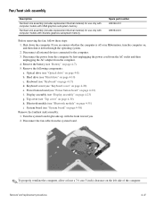
... with discrete graphics subsystem memory Spare part number 489126-001 489154-001 Before removing the fan, follow these steps: 1. Power button board (see "Bluetooth module" on page 4-22) f. Disconnect the fan cable from the computer. 4. Remove the following components: a. Bluetooth module (see ... h. Remove the battery (see "Top cover" on page 4-7). 5. Display assembly (see "Optical drive" on page 4-23) g. Fan/heat sink assembly Description Fan/heat sink assembly (includes replacement thermal material) for use only with computer models with UMA graphics subsystem memory...
... with discrete graphics subsystem memory Spare part number 489126-001 489154-001 Before removing the fan, follow these steps: 1. Power button board (see "Bluetooth module" on page 4-22) f. Disconnect the fan cable from the computer. 4. Remove the following components: a. Bluetooth module (see ... h. Remove the battery (see "Top cover" on page 4-7). 5. Display assembly (see "Optical drive" on page 4-23) g. Fan/heat sink assembly Description Fan/heat sink assembly (includes replacement thermal material) for use only with computer models with UMA graphics subsystem memory...

Service Guide
Page 81
... tighten the screws in the 1-2-3-4 sequence indicated. Loosen the 4 Phillips PM2.0x11.0 spring-loaded captive screws 1 that secure the fan/heat sink assembly. 5. Remove the fan/heat sink assembly 2 by lifting it straight up . ✎ Steps 6 through 5 apply only to computer models equipped with graphics... subsystems with the fan assembly toward you may need to move the fan/heat sink assembly from side to side to detach the assembly. 3. Remove the fan/heat sink assembly 2 by lifting it straight up . Turn the system ...
... tighten the screws in the 1-2-3-4 sequence indicated. Loosen the 4 Phillips PM2.0x11.0 spring-loaded captive screws 1 that secure the fan/heat sink assembly. 5. Remove the fan/heat sink assembly 2 by lifting it straight up . ✎ Steps 6 through 5 apply only to computer models equipped with graphics... subsystems with the fan assembly toward you may need to move the fan/heat sink assembly from side to side to detach the assembly. 3. Remove the fan/heat sink assembly 2 by lifting it straight up . Turn the system ...
Service Guide
Page 82
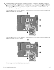
...The following illustration shows the replacement thermal material locations for computer models equipped with graphics subsystems with all system board, fan/heat sink assembly, and processor spare part kits. The following illustration shows the replacement thermal material locations for computer models... procedures 4-43 Replacement thermal grease and pads are located on the section of the fan/heat sink 3 that services the processor 2. Reverse this procedure to install the fan/heat sink assembly. ✎ The thermal material must be thoroughly cleaned from the surfaces...
...The following illustration shows the replacement thermal material locations for computer models equipped with graphics subsystems with all system board, fan/heat sink assembly, and processor spare part kits. The following illustration shows the replacement thermal material locations for computer models... procedures 4-43 Replacement thermal grease and pads are located on the section of the fan/heat sink 3 that services the processor 2. Reverse this procedure to install the fan/heat sink assembly. ✎ The thermal material must be thoroughly cleaned from the surfaces...

Service Guide
Page 84
... assembly (see "Fan/heat sink assembly" on the processor slot 4. Lift the processor 2 straight up and remove it. ✎ When you hear a click. 2. Top cover (see "Bluetooth module" ...
... assembly (see "Fan/heat sink assembly" on the processor slot 4. Lift the processor 2 straight up and remove it. ✎ When you hear a click. 2. Top cover (see "Bluetooth module" ...
Service Guide
Page 89
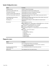
Setup Utility 5-4 Enable/disable Card Reader/1394 Power Saving. When enabled, the computer fan will always be on a secondary hard drive. System Configuration menu Select Language Support Button Sound (select models only) Virtualization Technology Processor C4 State (...select models only) LAN Power Saving (select models only) Card Reader/1394 Power Saving (select models only) Fan Always On Boot Options To do this Run a comprehensive self-test on the hard drive. ✎ On models with two hard drives, this Change the...
Setup Utility 5-4 Enable/disable Card Reader/1394 Power Saving. When enabled, the computer fan will always be on a secondary hard drive. System Configuration menu Select Language Support Button Sound (select models only) Virtualization Technology Processor C4 State (...select models only) LAN Power Saving (select models only) Card Reader/1394 Power Saving (select models only) Fan Always On Boot Options To do this Run a comprehensive self-test on the hard drive. ✎ On models with two hard drives, this Change the...
Service Guide
Page 111
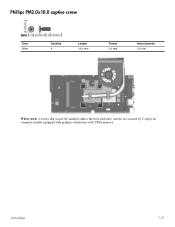
Phillips PM2.0x10.0 captive screw Color Silver Quantity 4 Length 10.0 mm Thread 2.0 mm Head diameter 5.0 mm Where used: 4 screws that secure the fan/heat sink to the base enclosure (screws are secured by C-clips) on computer models equipped with graphics subsystems with UMA memory Screw listing 7-15
Phillips PM2.0x10.0 captive screw Color Silver Quantity 4 Length 10.0 mm Thread 2.0 mm Head diameter 5.0 mm Where used: 4 screws that secure the fan/heat sink to the base enclosure (screws are secured by C-clips) on computer models equipped with graphics subsystems with UMA memory Screw listing 7-15
Service Guide
Page 112
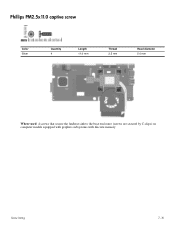
Phillips PM2.5x11.0 captive screw Color Silver Quantity 4 Length 11.0 mm Thread 2.5 mm Head diameter 5.0 mm Where used: 4 screws that secure the fan/heat sink to the base enclosure (screws are secured by C-clips) on computer models equipped with graphics subsystems with discrete memory Screw listing 7-16
Phillips PM2.5x11.0 captive screw Color Silver Quantity 4 Length 11.0 mm Thread 2.5 mm Head diameter 5.0 mm Where used: 4 screws that secure the fan/heat sink to the base enclosure (screws are secured by C-clips) on computer models equipped with graphics subsystems with discrete memory Screw listing 7-16
Service Guide
Page 131
..., 4-8 specifications 6-4 E electrostatic discharge 4-2 esc key 2-4 Ethernet, product description 1-4 external media cards, product description 1-5 external monitor port location 2-7 pin assignments 9-2 F f11 recovery 8-4 factory state, recovering to 8-1 fan removal 4-41 spare part number 3-4, 3-15, 4-41 feet locations 4-6 spare part number 4-6 fn key 2-4 front components 2-6 function keys 2-4 G graphics, product description 1-2, 1-3 grounding equipment 4-4 H hard drive...
..., 4-8 specifications 6-4 E electrostatic discharge 4-2 esc key 2-4 Ethernet, product description 1-4 external media cards, product description 1-5 external monitor port location 2-7 pin assignments 9-2 F f11 recovery 8-4 factory state, recovering to 8-1 fan removal 4-41 spare part number 3-4, 3-15, 4-41 feet locations 4-6 spare part number 4-6 fn key 2-4 front components 2-6 function keys 2-4 G graphics, product description 1-2, 1-3 grounding equipment 4-4 H hard drive...


