Service Guide
Page 11
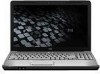
... network interface X card (NIC) Realtek 8102E X Wireless Integrated WLAN options by way of wireless module: 2 wireless antennae built into display X assembly Support for no-WLAN option X Presario CQ60 Intel Discrete X HP G60 Intel UMA X X X X X X X X X X X X X X X X X X X X X X X X X X X X X X X X X X X X X X X X X HP G60 Intel Discrete X X X X X X X X X X X X X X X X X X X X X Presario HP G60 CQ60 AMD UMA AMD UMA X X X X X X X X X X X X X X X X X X X X X X X X X X X X X X X X X X X X X X (Continued...
... network interface X card (NIC) Realtek 8102E X Wireless Integrated WLAN options by way of wireless module: 2 wireless antennae built into display X assembly Support for no-WLAN option X Presario CQ60 Intel Discrete X HP G60 Intel UMA X X X X X X X X X X X X X X X X X X X X X X X X X X X X X X X X X X X X X X X X X HP G60 Intel Discrete X X X X X X X X X X X X X X X X X X X X X Presario HP G60 CQ60 AMD UMA AMD UMA X X X X X X X X X X X X X X X X X X X X X X X X X X X X X X X X X X X X X X (Continued...
Service Guide
Page 12
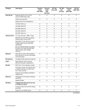
...-Wh battery X Security cable slot X Presario CQ60 Intel Discrete HP G60 Intel UMA X X X X X X X X X X X X X X X X X X X X X X X X X X X X X X X X X X X X X X X X X X X X HP G60 Intel Discrete X X X X X X X X X X X X X X X X X X X X X X Presario HP G60 CQ60 AMD UMA AMD UMA X X X X X X X X X X X X X X X X X X X X X X X X X X X X X X X X X X X X X X X X X X X X X X (Continued) Product description 1-5 Category Wireless (cont.) External media cards Ports Docking Keyboard/ TouchPad Power requirements...
...-Wh battery X Security cable slot X Presario CQ60 Intel Discrete HP G60 Intel UMA X X X X X X X X X X X X X X X X X X X X X X X X X X X X X X X X X X X X X X X X X X X X HP G60 Intel Discrete X X X X X X X X X X X X X X X X X X X X X X Presario HP G60 CQ60 AMD UMA AMD UMA X X X X X X X X X X X X X X X X X X X X X X X X X X X X X X X X X X X X X X X X X X X X X X (Continued) Product description 1-5 Category Wireless (cont.) External media cards Ports Docking Keyboard/ TouchPad Power requirements...
Service Guide
Page 14
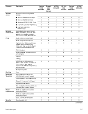
...areas immediately around the antennae free from one or more wireless devices. ✎ The antennae are located in use. Records audio and video and captures still photographs. On: The integrated webcam is on. To see wireless regulatory notices, refer to your country or region. Top... components Display components 2 External component identification Item Component 1 Internal display switch 2 Wireless antennae (2) (select models only) 3 Integrated webcam light (select models only) 4 Integrated webcam (select models only) 5 Internal microphone...
...areas immediately around the antennae free from one or more wireless devices. ✎ The antennae are located in use. Records audio and video and captures still photographs. On: The integrated webcam is on. To see wireless regulatory notices, refer to your country or region. Top... components Display components 2 External component identification Item Component 1 Internal display switch 2 Wireless antennae (2) (select models only) 3 Integrated webcam light (select models only) 4 Integrated webcam (select models only) 5 Internal microphone...
Service Guide
Page 15
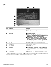
... being accessed. 4 TouchPad light White: TouchPad is enabled. 5 Caps lock light On: Caps lock is on. 6 Wireless light 7 Num lock light ■ Blue: An integrated wireless device, such as a wireless local area network (WLAN) device and/or a Bluetooth® device, is turned on the power button is visible only... Sleep state. ■ Off: The computer is off or in the computer are turned off. The light on . ■ Amber: All wireless devices are fully charged. If the computer is not plugged into an external power source, the light is turned off when all batteries in Hibernation...
... being accessed. 4 TouchPad light White: TouchPad is enabled. 5 Caps lock light On: Caps lock is on. 6 Wireless light 7 Num lock light ■ Blue: An integrated wireless device, such as a wireless local area network (WLAN) device and/or a Bluetooth® device, is turned on the power button is visible only... Sleep state. ■ Off: The computer is off or in the computer are turned off. The light on . ■ Amber: All wireless devices are fully charged. If the computer is not plugged into an external power source, the light is turned off when all batteries in Hibernation...
Service Guide
Page 16
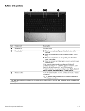
For information about your power settings, select Start > Control Panel > System and Maintenance > Power Options. Turns the wireless feature on , press the button briefly to initiate Sleep. ■ When the computer is in the Sleep state, press the button ... 2-3 Buttons and speakers Item Component 1 Speakers (2) Description Produce sound. 2 Power button* 3 Wireless button ■ When the computer is off, press the button to turn off , but does not create a wireless connection. ✎ A wireless network must be set up in order to the user guides located in Hibernation, press the...
For information about your power settings, select Start > Control Panel > System and Maintenance > Power Options. Turns the wireless feature on , press the button briefly to initiate Sleep. ■ When the computer is in the Sleep state, press the button ... 2-3 Buttons and speakers Item Component 1 Speakers (2) Description Produce sound. 2 Power button* 3 Wireless button ■ When the computer is off, press the button to turn off , but does not create a wireless connection. ✎ A wireless network must be set up in order to the user guides located in Hibernation, press the...
Service Guide
Page 21
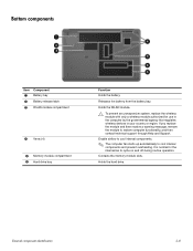
... computer functionality, and then contact technical support through Help and Support. It is normal for use in the computer by the governmental agency that regulates wireless devices in your country or region. Holds the hard drive. External component identification 2-8 Releases the battery from the battery bay. If you replace the module...
... computer functionality, and then contact technical support through Help and Support. It is normal for use in the computer by the governmental agency that regulates wireless devices in your country or region. Holds the hard drive. External component identification 2-8 Releases the battery from the battery bay. If you replace the module...

Service Guide
Page 31
... kit with webcam cable (not illustrated) (7) Wireless Antenna Kit (includes wireless antenna transceivers and cable) Wireless antenna cable (shown attached to transceivers) (8) Microphone and caps lock cable (includes receiver and cable) (9) Display enclosure (includes logo) For use only with HP G60 computer models For use only with silver HP G60 computer models For use only with Presario...
... kit with webcam cable (not illustrated) (7) Wireless Antenna Kit (includes wireless antenna transceivers and cable) Wireless antenna cable (shown attached to transceivers) (8) Microphone and caps lock cable (includes receiver and cable) (9) Display enclosure (includes logo) For use only with HP G60 computer models For use only with silver HP G60 computer models For use only with Presario...

Service Guide
Page 57
Remove the WLAN module 3 by pulling the module away from the wireless module. ✎ The black WLAN antenna cable is connected to the WLAN module "Aux" terminal. 3. Removal and replacement procedures 4-16 2. Reverse this procedure to the ...
Remove the WLAN module 3 by pulling the module away from the wireless module. ✎ The black WLAN antenna cable is connected to the WLAN module "Aux" terminal. 3. Removal and replacement procedures 4-16 2. Reverse this procedure to the ...
Service Guide
Page 63
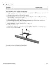
... and replacement procedures 4-22 Remove the two Phillips PM2.0x4.0 screws 1 that secure the power button board to install the power button board. Disconnect the wireless antenna cables from the computer. 4. Remove the keyboard (see "WLAN module" on , and then shut it down the computer. Remove the keyboard cover (see "Battery...
... and replacement procedures 4-22 Remove the two Phillips PM2.0x4.0 screws 1 that secure the power button board to install the power button board. Disconnect the wireless antenna cables from the computer. 4. Remove the keyboard (see "WLAN module" on , and then shut it down the computer. Remove the keyboard cover (see "Battery...
Service Guide
Page 65
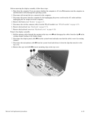
... 4-24 Disconnect the display panel cable 3 from the clips that the cable is off or in Hibernation, turn the computer on page 4-20). Disconnect the wireless antenna cables from the clip 2 in the top cover 1 and disengage the cables from the WLAN module (see "Keyboard" on page 4-15). 6. Remove the keyboard...
... 4-24 Disconnect the display panel cable 3 from the clips that the cable is off or in Hibernation, turn the computer on page 4-20). Disconnect the wireless antenna cables from the clip 2 in the top cover 1 and disengage the cables from the WLAN module (see "Keyboard" on page 4-15). 6. Remove the keyboard...
Service Guide
Page 134
... 5-4 boot order 5-4 bottom components 2-8 Index Index built-in device Bluetooth device radio 2-8 modem 1-4 wireless button 2-3 WLAN device radio 2-8 buttons power 2-3 wireless 2-3 C cables, service consideration 4-1 caps lock light 2-2 chipset, product description 1-2 CMOS clearing 4-4 ...bottom 2-8 buttons 2-3 display 2-1 front 2-6 keys 2-4 left-side 2-7 lights 2-2 rear 2-6 right-side 2-7 top 2-1 TouchPad 2-5 wireless antennae 2-1 computer feet locations 4-6 spare part number 4-6 computer specifications 6-1 connectors power 2-7 service consideration 4-1 creating recovery discs 8-1 creating...
... 5-4 boot order 5-4 bottom components 2-8 Index Index built-in device Bluetooth device radio 2-8 modem 1-4 wireless button 2-3 WLAN device radio 2-8 buttons power 2-3 wireless 2-3 C cables, service consideration 4-1 caps lock light 2-2 chipset, product description 1-2 CMOS clearing 4-4 ...bottom 2-8 buttons 2-3 display 2-1 front 2-6 keys 2-4 left-side 2-7 lights 2-2 rear 2-6 right-side 2-7 top 2-1 TouchPad 2-5 wireless antennae 2-1 computer feet locations 4-6 spare part number 4-6 computer specifications 6-1 connectors power 2-7 service consideration 4-1 creating recovery discs 8-1 creating...
Service Guide
Page 137
operating system 1-6 optical drives 1-4 panel 1-3 ports 1-5 power requirements 1-5 processors 1-1 product name 1-1 security 1-5 serviceability 1-6 TouchPad 2-5 video 2-7 webcam 1-4 wireless 1-4 product name 1-1, 3-1 R rear components 2-6 recovery methods f11 recovery 8-4 recovery discs 8-4 Recovery Manager 8-3 recovery partition 8-4 removal/replacement preliminaries 4-1 procedures 4-5 restore points 8-3 restoring factory settings 5-2 right-side ...
operating system 1-6 optical drives 1-4 panel 1-3 ports 1-5 power requirements 1-5 processors 1-1 product name 1-1 security 1-5 serviceability 1-6 TouchPad 2-5 video 2-7 webcam 1-4 wireless 1-4 product name 1-1, 3-1 R rear components 2-6 recovery methods f11 recovery 8-4 recovery discs 8-4 Recovery Manager 8-3 recovery partition 8-4 removal/replacement preliminaries 4-1 procedures 4-5 restore points 8-3 restoring factory settings 5-2 right-side ...


