Setup Utility - Windows Vista and Windows 7
Page 10
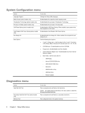
When enabled, the computer fan will always be on a secondary hard drive. Run a comprehensive self-test on . Enable/disable the ...NOTE: On models with two hard drives, this menu option is in intervals of the Setup Utility in DC mode. Enabled/disable Fan Always On. Enable/disable the processor C6 sleep state. Run a diagnostic test on the system memory. 6 Chapter 3 Setup Utility...(select models only) LAN Power Saving (select models only) Card Reader/1394 Power Saving (select models only) Fan Always On Boot Options To do this Run a comprehensive self-test on the hard drive.
When enabled, the computer fan will always be on a secondary hard drive. Run a comprehensive self-test on . Enable/disable the ...NOTE: On models with two hard drives, this menu option is in intervals of the Setup Utility in DC mode. Enabled/disable Fan Always On. Enable/disable the processor C6 sleep state. Run a diagnostic test on the system memory. 6 Chapter 3 Setup Utility...(select models only) LAN Power Saving (select models only) Card Reader/1394 Power Saving (select models only) Fan Always On Boot Options To do this Run a comprehensive self-test on the hard drive.
Setup Utility - Windows Vista and Windows 7
Page 11
... 6 boot order 6 button sound 6 C Card Reader Power Saving 6 changing the Setup Utility language 2 D Diagnostics menu 6 displaying system information 3 drives, boot order 6 E exiting the Setup Utility 4 F fan always on 6 fingerprint reader 1 H hard drive self test 6 L LAN Power Saving 6 language support 6 M Main menu 5 memory test 6 N navigating in the Setup Utility 2 P passwords 5 power-on...
... 6 boot order 6 button sound 6 C Card Reader Power Saving 6 changing the Setup Utility language 2 D Diagnostics menu 6 displaying system information 3 drives, boot order 6 E exiting the Setup Utility 4 F fan always on 6 fingerprint reader 1 H hard drive self test 6 L LAN Power Saving 6 language support 6 M Main menu 5 memory test 6 N navigating in the Setup Utility 2 P passwords 5 power-on...
Notebook Tour - Windows Vista
Page 12
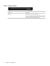
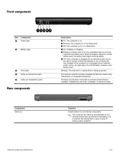
NOTE: The computer fan starts up automatically to cycle on and off during routine operation. 6 Chapter 2 Components It is normal for the internal fan to cool internal components and prevent overheating. Rear components Component Vents (2) Description Enables airflow to cool internal components.
NOTE: The computer fan starts up automatically to cycle on and off during routine operation. 6 Chapter 2 Components It is normal for the internal fan to cool internal components and prevent overheating. Rear components Component Vents (2) Description Enables airflow to cool internal components.
Notebook Tour - Windows Vista
Page 15
... module and then receive a warning message, remove the module to cycle on and off during routine operation. NOTE: The computer fan starts up automatically to cool internal components. Holds the WLAN module. Releases the battery from the battery bay. Holds the hard ...and prevent overheating. CAUTION: To prevent an unresponsive system, replace the wireless module only with a wireless module authorized for the internal fan to restore computer functionality, and then contact technical support through Help and Support. Contains the memory module slots. Bottom components Component (1)...
... module and then receive a warning message, remove the module to cycle on and off during routine operation. NOTE: The computer fan starts up automatically to cool internal components. Holds the WLAN module. Releases the battery from the battery bay. Holds the hard ...and prevent overheating. CAUTION: To prevent an unresponsive system, replace the wireless module only with a wireless module authorized for the internal fan to restore computer functionality, and then contact technical support through Help and Support. Contains the memory module slots. Bottom components Component (1)...
Service Guide
Page 5
... cover 4-30 TouchPad on/off button board and board bracket 4-32 Audio board 4-34 Bluetooth module 4-35 Speakers 4-36 USB board 4-37 System board 4-38 Fan/heat sink assembly 4-41 Processor 4-44 Power connector cable 4-46 5 Setup Utility Starting the Setup Utility 5-1 Changing the language of the Setup Utility 5-1 Navigating and...
... cover 4-30 TouchPad on/off button board and board bracket 4-32 Audio board 4-34 Bluetooth module 4-35 Speakers 4-36 USB board 4-37 System board 4-38 Fan/heat sink assembly 4-41 Processor 4-44 Power connector cable 4-46 5 Setup Utility Starting the Setup Utility 5-1 Changing the language of the Setup Utility 5-1 Navigating and...
Service Guide
Page 19
... ■ On: The computer is on and off during routine operation. Function Enable airflow to cool internal components. ✎ The computer fan starts up automatically to optional powered stereo speakers, headphones, ear buds, a headset, or television audio. Blinking: The hard drive or optical... components and prevent overheating. Connects an optional computer headset microphone, stereo array microphone, or monaural microphone. It is normal for the internal fan to cycle on . ■ Blinking: The computer is in the Sleep state. ■ Off: The computer is the only available...
... ■ On: The computer is on and off during routine operation. Function Enable airflow to cool internal components. ✎ The computer fan starts up automatically to optional powered stereo speakers, headphones, ear buds, a headset, or television audio. Blinking: The hard drive or optical... components and prevent overheating. Connects an optional computer headset microphone, stereo array microphone, or monaural microphone. It is normal for the internal fan to cycle on . ■ Blinking: The computer is in the Sleep state. ■ Off: The computer is the only available...
Service Guide
Page 21
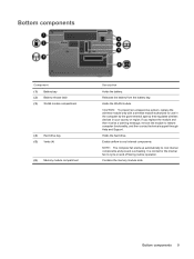
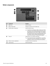
...Holds the hard drive. Releases the battery from the battery bay. Enable airflow to cool internal components. ✎ The computer fan starts up automatically to restore computer functionality, and then contact technical support through Help and Support. It is normal for use in.... Holds the WLAN module. Ä To prevent an unresponsive system, replace the wireless module with only a wireless module authorized for the internal fan to cycle on and off during routine operation. Bottom components Item Component 1 Battery bay 2 Battery release latch 3 WLAN module compartment 4 Vents ...
...Holds the hard drive. Releases the battery from the battery bay. Enable airflow to cool internal components. ✎ The computer fan starts up automatically to restore computer functionality, and then contact technical support through Help and Support. It is normal for use in.... Holds the WLAN module. Ä To prevent an unresponsive system, replace the wireless module with only a wireless module authorized for the internal fan to cycle on and off during routine operation. Bottom components Item Component 1 Battery bay 2 Battery release latch 3 WLAN module compartment 4 Vents ...

Service Guide
Page 25
...) 496830-001 (5) Top cover (includes TouchPad board) 506849-001 (6) TouchPad on/off button board (includes cables) 496832-001 (7) Fan/heat sink assembly for use with UMA systems (includes replacement thermal material) 489126-001 Fan/heat sink assembly for use with Discrete systems (includes replacement thermal material) 489154-001 (8) TouchPad board bracket 489119...
...) 496830-001 (5) Top cover (includes TouchPad board) 506849-001 (6) TouchPad on/off button board (includes cables) 496832-001 (7) Fan/heat sink assembly for use with UMA systems (includes replacement thermal material) 489126-001 Fan/heat sink assembly for use with Discrete systems (includes replacement thermal material) 489154-001 (8) TouchPad board bracket 489119...
Service Guide
Page 36
... for use in modem, Digital Media Slot, HDMI port, and replacement thermal material) Webcam TouchPad board bracket Fan/heat sink for use with UMA systems (includes replacement thermal material) Audio board (includes audio board cable) Fan/heat sink for use with discrete systems (includes replacement thermal material) (Continued) Intel Core2 Duo P8400...
... for use in modem, Digital Media Slot, HDMI port, and replacement thermal material) Webcam TouchPad board bracket Fan/heat sink for use with UMA systems (includes replacement thermal material) Audio board (includes audio board cable) Fan/heat sink for use with discrete systems (includes replacement thermal material) (Continued) Intel Core2 Duo P8400...
Service Guide
Page 80
... (see "RTC battery" on page 4-12) ■ Memory module (see "Memory module" on page 4-13) ■ WLAN module (see "WLAN module" on page 4-15) ■ Fan/heat sink assembly (see "Fan/heat sink assembly" on page 4-41) ■ Processor (see "Processor" on the optical extension board. 5.
... (see "RTC battery" on page 4-12) ■ Memory module (see "Memory module" on page 4-13) ■ WLAN module (see "WLAN module" on page 4-15) ■ Fan/heat sink assembly (see "Fan/heat sink assembly" on page 4-41) ■ Processor (see "Processor" on the optical extension board. 5.
Service Guide
Page 82
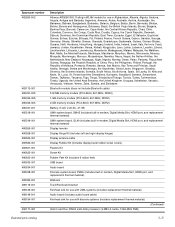
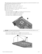
... a 7.6-cm (3-inch) clearance on the left side of the computer. Keyboard (see "System board" on page 4-38) Remove the fan/heat sink assembly: 1. Turn the system board right-side up, with discrete graphics subsystem memory Spare part number 489126-001 489154-001 Before... removing the fan, follow these steps: 1. Disconnect the fan cable from the computer. 4. System board (see "Keyboard" on page 4-17) d. Removal and replacement procedures 4-41 Fan/heat sink assembly Description Fan/heat sink assembly (includes replacement thermal material) for...
... a 7.6-cm (3-inch) clearance on the left side of the computer. Keyboard (see "System board" on page 4-38) Remove the fan/heat sink assembly: 1. Turn the system board right-side up, with discrete graphics subsystem memory Spare part number 489126-001 489154-001 Before... removing the fan, follow these steps: 1. Disconnect the fan cable from the computer. 4. System board (see "Keyboard" on page 4-17) d. Removal and replacement procedures 4-41 Fan/heat sink assembly Description Fan/heat sink assembly (includes replacement thermal material) for...
Service Guide
Page 83
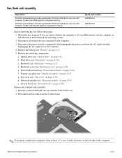
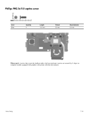
...indicated. Loosen the 4 Phillips PM2.0x11.0 spring-loaded captive screws 1 that secure the fan/heat sink assembly. 5. ✎ Due to the adhesive quality of the thermal material located between the fan/heat sink assembly and system board components, you . Å WARNING: To avoid ... sequence stamped into the heat sink, loosen the four Phillips PM2.0x10.0 spring-loaded captive screws 1 that secure the fan/heatsink assembly. 7. Removal and replacement procedures 4-42 Remove the fan/heat sink assembly 2 by lifting it straight up . ✎ Steps 6 through 5 apply only to computer models ...
...indicated. Loosen the 4 Phillips PM2.0x11.0 spring-loaded captive screws 1 that secure the fan/heat sink assembly. 5. ✎ Due to the adhesive quality of the thermal material located between the fan/heat sink assembly and system board components, you . Å WARNING: To avoid ... sequence stamped into the heat sink, loosen the four Phillips PM2.0x10.0 spring-loaded captive screws 1 that secure the fan/heatsink assembly. 7. Removal and replacement procedures 4-42 Remove the fan/heat sink assembly 2 by lifting it straight up . ✎ Steps 6 through 5 apply only to computer models ...
Service Guide
Page 84
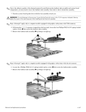
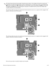
...The thermal material must be thoroughly cleaned from the surfaces of the fan/heat sink and the system board components each time the fan/heat sink is located on the section of the fan/heat sink 1 that services the Northbridge chip 4. The following illustration... shows the replacement thermal material locations for computer models equipped with graphics subsystems with all system board, fan/heat sink assembly, and processor spare part kits. The following illustration shows the replacement thermal material locations for computer models ...
...The thermal material must be thoroughly cleaned from the surfaces of the fan/heat sink and the system board components each time the fan/heat sink is located on the section of the fan/heat sink 1 that services the Northbridge chip 4. The following illustration... shows the replacement thermal material locations for computer models equipped with graphics subsystems with all system board, fan/heat sink assembly, and processor spare part kits. The following illustration shows the replacement thermal material locations for computer models ...
Service Guide
Page 86
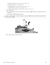
... gold triangle on the processor 3 must be aligned with the triangle embossed on page 4-35) j. Display assembly (see "Fan/heat sink assembly" on page 4-38) k. Use a flat-bladed screwdriver to install the processor. Fan/heat sink assembly (see "Display assembly" on page 4-30) i. Removal and replacement procedures 4-45 System board (see "Bluetooth...
... gold triangle on the processor 3 must be aligned with the triangle embossed on page 4-35) j. Display assembly (see "Fan/heat sink assembly" on page 4-38) k. Use a flat-bladed screwdriver to install the processor. Fan/heat sink assembly (see "Display assembly" on page 4-30) i. Removal and replacement procedures 4-45 System board (see "Bluetooth...
Service Guide
Page 91
...only) Virtualization Technology Processor C4 State (select models only) LAN Power Saving (select models only) Card Reader/1394 Power Saving (select models only) Fan Always On Boot Options To do this Run a comprehensive self-test on the hard drive. ✎ On models with two hard drives, this ...the Setup Utility language. Enable/disable the processor C4 sleep state. Run a comprehensive self-test on the system memory. When enabled, the computer fan will always be on. When enabled, saves power when the computer is in DC mode. When enabled, saves power when the computer is in...
...only) Virtualization Technology Processor C4 State (select models only) LAN Power Saving (select models only) Card Reader/1394 Power Saving (select models only) Fan Always On Boot Options To do this Run a comprehensive self-test on the hard drive. ✎ On models with two hard drives, this ...the Setup Utility language. Enable/disable the processor C4 sleep state. Run a comprehensive self-test on the system memory. When enabled, the computer fan will always be on. When enabled, saves power when the computer is in DC mode. When enabled, saves power when the computer is in...
Service Guide
Page 114
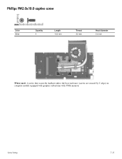
Phillips PM2.0x10.0 captive screw Color Silver Quantity 4 Length 10.0 mm Thread 2.0 mm Head diameter 5.0 mm Where used: 4 screws that secure the fan/heat sink to the base enclosure (screws are secured by C-clips) on computer models equipped with graphics subsystems with UMA memory Screw listing 7-15
Phillips PM2.0x10.0 captive screw Color Silver Quantity 4 Length 10.0 mm Thread 2.0 mm Head diameter 5.0 mm Where used: 4 screws that secure the fan/heat sink to the base enclosure (screws are secured by C-clips) on computer models equipped with graphics subsystems with UMA memory Screw listing 7-15
Service Guide
Page 115
Phillips PM2.5x11.0 captive screw Color Silver Quantity 4 Length 11.0 mm Thread 2.5 mm Head diameter 5.0 mm Where used: 4 screws that secure the fan/heat sink to the base enclosure (screws are secured by C-clips) on computer models equipped with graphics subsystems with discrete memory Screw listing 7-16
Phillips PM2.5x11.0 captive screw Color Silver Quantity 4 Length 11.0 mm Thread 2.5 mm Head diameter 5.0 mm Where used: 4 screws that secure the fan/heat sink to the base enclosure (screws are secured by C-clips) on computer models equipped with graphics subsystems with discrete memory Screw listing 7-16
Service Guide
Page 135
..., 4-8 specifications 6-4 E electrostatic discharge 4-2 esc key 2-4 Ethernet, product description 1-4 external media cards, product description 1-5 external monitor port location 2-7 pin assignments 9-2 F f11 recovery 8-4 factory state, recovering to 8-1 fan removal 4-41 spare part number 3-4, 3-15, 4-41 feet locations 4-6 spare part number 4-6 fn key 2-4 front components 2-6 function keys 2-4 G graphics, product description 1-2, 1-3 grounding equipment 4-4 H hard drive...
..., 4-8 specifications 6-4 E electrostatic discharge 4-2 esc key 2-4 Ethernet, product description 1-4 external media cards, product description 1-5 external monitor port location 2-7 pin assignments 9-2 F f11 recovery 8-4 factory state, recovering to 8-1 fan removal 4-41 spare part number 3-4, 3-15, 4-41 feet locations 4-6 spare part number 4-6 fn key 2-4 front components 2-6 function keys 2-4 G graphics, product description 1-2, 1-3 grounding equipment 4-4 H hard drive...


