Wireless (Select Models Only) - Windows Vista
Page 19
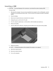
Then shut down the computer. Unplug the power cord from the AC outlet. 5. Remove the battery. 7. NOTE: HP Mobile Broadband will be disabled if the battery is off or in Hibernation, turn the computer on by pressing the power button. Reconnect external devices. 11. If you . ...minimal force when inserting a SIM. Turn on a flat surface, with the battery bay toward you are not sure whether the computer is not replaced. 9. Inserting a SIM CAUTION: To prevent damage to the computer. 4. Close the display. 3. Replace the battery. To insert a SIM: 1. Insert the SIM into the SIM slot, ...
Then shut down the computer. Unplug the power cord from the AC outlet. 5. Remove the battery. 7. NOTE: HP Mobile Broadband will be disabled if the battery is off or in Hibernation, turn the computer on by pressing the power button. Reconnect external devices. 11. If you . ...minimal force when inserting a SIM. Turn on a flat surface, with the battery bay toward you are not sure whether the computer is not replaced. 9. Inserting a SIM CAUTION: To prevent damage to the computer. 4. Close the display. 3. Replace the battery. To insert a SIM: 1. Insert the SIM into the SIM slot, ...
Wireless (Select Models Only) - Windows Vista
Page 20
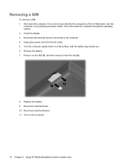
...system. 2. Press in Hibernation, turn the computer on by pressing the power button. Remove the battery. 7. Disconnect all external devices connected to the computer. 4. Reconnect external power. 10. If you . 6. Replace the battery. 9. Turn on the SIM (1), and then remove it from the AC outlet. 5. Then ...shut down on a flat surface, with the battery bay toward you are not sure whether the computer is off or in on the computer. 14 Chapter 3 Using HP Mobile Broadband (select models only) Shut down the computer. Reconnect external devices. 11...
...system. 2. Press in Hibernation, turn the computer on by pressing the power button. Remove the battery. 7. Disconnect all external devices connected to the computer. 4. Reconnect external power. 10. If you . 6. Replace the battery. 9. Turn on the SIM (1), and then remove it from the AC outlet. 5. Then ...shut down on a flat surface, with the battery bay toward you are not sure whether the computer is off or in on the computer. 14 Chapter 3 Using HP Mobile Broadband (select models only) Shut down the computer. Reconnect external devices. 11...
Drives - Windows Vista
Page 14
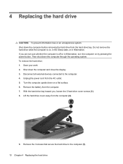
...Lift the hard drive cover away from the hard drive bay. Remove the 3 screws that secure the hard drive to the computer. 4. 4 Replacing the hard drive CAUTION: To prevent information loss or an unresponsive system: Shut down the computer before removing the hard drive from the computer ...(2). 9. Shut down the computer through the operating system. Remove the battery from the AC outlet. 5. Unplug the power cord from the computer. 7. Then shut down the computer and close the display. 3. Save your...
...Lift the hard drive cover away from the hard drive bay. Remove the 3 screws that secure the hard drive to the computer. 4. 4 Replacing the hard drive CAUTION: To prevent information loss or an unresponsive system: Shut down the computer before removing the hard drive from the computer ...(2). 9. Shut down the computer through the operating system. Remove the battery from the AC outlet. 5. Unplug the power cord from the computer. 7. Then shut down the computer and close the display. 3. Save your...
Memory Modules - Windows Vista and Windows 7
Page 7
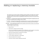
... operating system. 3. Turn the computer upside down on the bottom of electric shock and damage to the computer. 4. WARNING! To add or replace a memory module: 1. To reduce the risk of the computer. CAUTION: Electrostatic discharge (ESD) can be sure that you are the same size.... Disconnect all external devices connected to the equipment, unplug the power cord and remove all batteries before installing a memory module. Adding or replacing a memory module The computer has one memory module compartment, which is off or in the primary memory module slot....
... operating system. 3. Turn the computer upside down on the bottom of electric shock and damage to the computer. 4. WARNING! To add or replace a memory module: 1. To reduce the risk of the computer. CAUTION: Electrostatic discharge (ESD) can be sure that you are the same size.... Disconnect all external devices connected to the equipment, unplug the power cord and remove all batteries before installing a memory module. Adding or replacing a memory module The computer has one memory module compartment, which is off or in the primary memory module slot....

Memory Modules - Windows Vista and Windows 7
Page 10
Turn on the computer. 4 Adding or replacing a memory module Replace the battery. 15. 14. Reconnect external power and external devices. 16.
Turn on the computer. 4 Adding or replacing a memory module Replace the battery. 15. 14. Reconnect external power and external devices. 16.
Notebook Tour - Windows Vista
Page 15
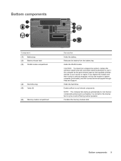
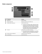
... components. Contains the memory module slots. Bottom components 9 Enable airflow to cool internal components and prevent overheating. If you replace the module and then receive a warning message, remove the module to cycle on and off during routine operation. Holds the... hard drive. Bottom components Component (1) Battery bay (2) Battery release latch (3) WLAN module compartment (4) Hard drive bay (5) Vents (4) (6) Memory module compartment Description Holds the battery. It is normal for use in the computer by the governmental agency...
... components. Contains the memory module slots. Bottom components 9 Enable airflow to cool internal components and prevent overheating. If you replace the module and then receive a warning message, remove the module to cycle on and off during routine operation. Holds the... hard drive. Bottom components Component (1) Battery bay (2) Battery release latch (3) WLAN module compartment (4) Hard drive bay (5) Vents (4) (6) Memory module compartment Description Holds the battery. It is normal for use in the computer by the governmental agency...

Power Management - Windows Vista
Page 10
... reduce potential safety issues, use the fn+f8 hotkey or reconnect the AC adapter. To increase display brightness, use only the battery provided with the computer, a replacement battery provided by HP, or a compatible battery purchased from external power. NOTE: The display brightness is plugged into external AC power, the computer runs on how you disconnect...
... reduce potential safety issues, use the fn+f8 hotkey or reconnect the AC adapter. To increase display brightness, use only the battery provided with the computer, a replacement battery provided by HP, or a compatible battery purchased from external power. NOTE: The display brightness is plugged into external AC power, the computer runs on how you disconnect...
Power Management - Windows Vista
Page 21
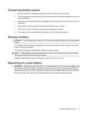
...an external power source, when you are not using it if it separately. Calibrate a battery before returning it to a battery, do not disassemble, crush, or puncture a battery; NOTE: A stored battery should be unused and unplugged from external power for one month or more than 50 percent,..., or shut down the computer. Disposing of time. If the capacity is less than 2 weeks, remove the battery and store it has been stored for more . Replace the battery only with a battery approved for battery disposal information. If a computer will be checked every 6 months.
...an external power source, when you are not using it if it separately. Calibrate a battery before returning it to a battery, do not disassemble, crush, or puncture a battery; NOTE: A stored battery should be unused and unplugged from external power for one month or more than 50 percent,..., or shut down the computer. Disposing of time. If the capacity is less than 2 weeks, remove the battery and store it has been stored for more . Replace the battery only with a battery approved for battery disposal information. If a computer will be checked every 6 months.

Power Management - Windows Vista
Page 22
... following conditions: WARNING! To reduce potential safety issues, use only the AC adapter provided with the computer, a replacement AC adapter provided by HP, or a compatible AC adapter purchased from HP. Connect the computer to save battery life. To increase display brightness, press the fn+f8 hotkey or reconnect the AC adapter. 18 Chapter 3 Using...
... following conditions: WARNING! To reduce potential safety issues, use only the AC adapter provided with the computer, a replacement AC adapter provided by HP, or a compatible AC adapter purchased from HP. Connect the computer to save battery life. To increase display brightness, press the fn+f8 hotkey or reconnect the AC adapter. 18 Chapter 3 Using...

Power Management - Windows Vista
Page 24
.... If the computer is possible. 1. Shut down the computer under any of the following conditions: ● When you need to replace the battery or access components inside the computer ● When you are unable to use the preceding shutdown procedures, try the following emergency procedures ...and then click the arrow next to a USB port ● When the computer will be unused and disconnected from external power and remove the battery. 20 Chapter 4 Shutting down . Save your work and close all open programs. 2. 4 Shutting down the computer CAUTION: Unsaved information will ...
.... If the computer is possible. 1. Shut down the computer under any of the following conditions: ● When you need to replace the battery or access components inside the computer ● When you are unable to use the preceding shutdown procedures, try the following emergency procedures ...and then click the arrow next to a USB port ● When the computer will be unused and disconnected from external power and remove the battery. 20 Chapter 4 Shutting down . Save your work and close all open programs. 2. 4 Shutting down the computer CAUTION: Unsaved information will ...
Service Guide
Page 4
... storage devices 3-12 Miscellaneous parts 3-13 Sequential part number listing 3-14 4 Removal and replacement procedures Preliminary replacement requirements 4-1 Tools required 4-1 Service considerations 4-1 Grounding guidelines 4-2 Unknown user password 4-4 Component replacement procedures 4-5 Serial number 4-5 Computer feet 4-6 Battery 4-7 Optical drive 4-8 Hard drive 4-10 RTC battery 4-12 Memory module 4-13 WLAN module 4-15 Keyboard 4-17 Keyboard cover 4-20 Contents...
... storage devices 3-12 Miscellaneous parts 3-13 Sequential part number listing 3-14 4 Removal and replacement procedures Preliminary replacement requirements 4-1 Tools required 4-1 Service considerations 4-1 Grounding guidelines 4-2 Unknown user password 4-4 Component replacement procedures 4-5 Serial number 4-5 Computer feet 4-6 Battery 4-7 Optical drive 4-8 Hard drive 4-10 RTC battery 4-12 Memory module 4-13 WLAN module 4-15 Keyboard 4-17 Keyboard cover 4-20 Contents...
Service Guide
Page 13
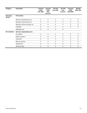
...: Windows Vista Business 32 Windows Vista Premium 32 Windows Vista Home Basic 32 FreeDOS RedFlag Linux End-user replaceable parts: AC adapter Battery (system) Hard drive Memory module Optical drive WLAN module Presario CQ60 Intel UMA Presario CQ60 Intel Discrete HP G60 Intel UMA HP G60 Intel Discrete Presario HP G60 CQ60 AMD UMA AMD UMA X X X X X X X X X X X X X X X X X X X X X X X X X X X X X X X X X X X X X X X X X X X X X X X X X X X X X X X X X X X X X X X X Product description...
...: Windows Vista Business 32 Windows Vista Premium 32 Windows Vista Home Basic 32 FreeDOS RedFlag Linux End-user replaceable parts: AC adapter Battery (system) Hard drive Memory module Optical drive WLAN module Presario CQ60 Intel UMA Presario CQ60 Intel Discrete HP G60 Intel UMA HP G60 Intel Discrete Presario HP G60 CQ60 AMD UMA AMD UMA X X X X X X X X X X X X X X X X X X X X X X X X X X X X X X X X X X X X X X X X X X X X X X X X X X X X X X X X X X X X X X X X Product description...
Service Guide
Page 21
... module authorized for the internal fan to cycle on and off during routine operation. Holds the hard drive. If you replace the module and then receive a warning message, remove the module to cool internal components and prevent overheating. It is ...regulates wireless devices in your country or region. Bottom components Item Component 1 Battery bay 2 Battery release latch 3 WLAN module compartment 4 Vents (4) 5 Memory module compartment 6 Hard drive bay Function Holds the battery. External component identification 2-8 Enable airflow to cool internal components. ✎ The...
... module authorized for the internal fan to cycle on and off during routine operation. Holds the hard drive. If you replace the module and then receive a warning message, remove the module to cool internal components and prevent overheating. It is ...regulates wireless devices in your country or region. Bottom components Item Component 1 Battery bay 2 Battery release latch 3 WLAN module compartment 4 Vents (4) 5 Memory module compartment 6 Hard drive bay Function Holds the battery. External component identification 2-8 Enable airflow to cool internal components. ✎ The...
Service Guide
Page 36
...-6400, 667-MHz, DDR2) 2-GB memory module (PC2-6400, 667-MHz, DDR2) Battery, 6-cell, 2.20-Ah, 47-Wh UMA system board, GM45 (includes built-in modem, Digital Media Slot, HDMI port, and replacement thermal material) UMA system board, GL40 (includes built-in modem, Digital Media Slot, HDMI...board Discrete system board, PM45 (includes built-in modem, Digital Media Slot, HDMI port, and replacement thermal material) Webcam TouchPad board bracket Fan/heat sink for use with UMA systems (includes replacement thermal material) Audio board (includes audio board cable) Fan/heat sink for use with discrete ...
...-6400, 667-MHz, DDR2) 2-GB memory module (PC2-6400, 667-MHz, DDR2) Battery, 6-cell, 2.20-Ah, 47-Wh UMA system board, GM45 (includes built-in modem, Digital Media Slot, HDMI port, and replacement thermal material) UMA system board, GL40 (includes built-in modem, Digital Media Slot, HDMI...board Discrete system board, PM45 (includes built-in modem, Digital Media Slot, HDMI port, and replacement thermal material) Webcam TouchPad board bracket Fan/heat sink for use with UMA systems (includes replacement thermal material) Audio board (includes audio board cable) Fan/heat sink for use with discrete ...
Service Guide
Page 45
...toe, or boot straps) can be used at all external devices connected to a grounded system. Remove the battery (see "RTC battery" on page 4-7). 5. Remove the real-time clock (RTC) battery (see "Battery" on page 4-12). 6. Wait approximately 5 minutes. To provide proper ground, wear a strap snugly against...turn the computer on both feet with a minimum of shoes or boots. Shut down through the operating system. 2. Removal and replacement procedures 4-4 Equipment guidelines Grounding equipment must be worn in contact with the skin. Wrist straps are unsure whether the computer is...
...toe, or boot straps) can be used at all external devices connected to a grounded system. Remove the battery (see "RTC battery" on page 4-7). 5. Remove the real-time clock (RTC) battery (see "Battery" on page 4-12). 6. Wait approximately 5 minutes. To provide proper ground, wear a strap snugly against...turn the computer on both feet with a minimum of shoes or boots. Shut down through the operating system. 2. Removal and replacement procedures 4-4 Equipment guidelines Grounding equipment must be worn in contact with the skin. Wrist straps are unsure whether the computer is...
Service Guide
Page 46
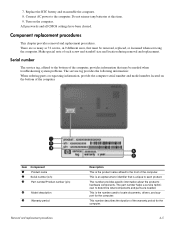
... 2 3 Component Product name Serial number (s/n) Part number/Product number (p/n) 4 Model description 5 Warranty period Removal and replacement procedures Description This is unique to the bottom of the computer. This number provides specific information about the product's hardware ... drivers, and support for the computer. 4-5 7. Replace the RTC battery and reassemble the computer. 8. Do not reinsert any batteries at this time. 9. Component replacement procedures This chapter provides removal and replacement procedures. Make special note of the warranty period for...
... 2 3 Component Product name Serial number (s/n) Part number/Product number (p/n) 4 Model description 5 Warranty period Removal and replacement procedures Description This is unique to the bottom of the computer. This number provides specific information about the product's hardware ... drivers, and support for the computer. 4-5 7. Replace the RTC battery and reassemble the computer. 8. Do not reinsert any batteries at this time. 9. Component replacement procedures This chapter provides removal and replacement procedures. Make special note of the warranty period for...
Service Guide
Page 48
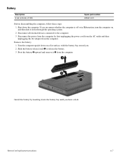
Disconnect all external devices connected to release the battery. 3. Removal and replacement procedures 4-7 Shut down through the operating system. 2. If you are unsure whether the computer is off or in Hibernation, turn the computer on a flat surface, with the battery bay toward you hear a click. Turn the computer upside down on , and then shut...
Disconnect all external devices connected to release the battery. 3. Removal and replacement procedures 4-7 Shut down through the operating system. 2. If you are unsure whether the computer is off or in Hibernation, turn the computer on a flat surface, with the battery bay toward you hear a click. Turn the computer upside down on , and then shut...
Service Guide
Page 49
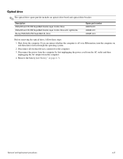
... power from the computer by first unplugging the power cord from the AC outlet and then unplugging the AC adapter from the computer. 4. Remove the battery (see"Battery" on , and then shut it down the computer. If you are unsure whether the computer is off or in Hibernation, turn the computer on... DVD±RW SuperMulti DL Drive Spare part number 498479-001 498480-001 498481-001 Before removing the optical drive, follow these steps: 1. Removal and replacement procedures 4-8 Optical drive ✎ The optical drive spare part kit includes an optical drive bezel and optical drive bracket.
... power from the computer by first unplugging the power cord from the AC outlet and then unplugging the AC adapter from the computer. 4. Remove the battery (see"Battery" on , and then shut it down the computer. If you are unsure whether the computer is off or in Hibernation, turn the computer on... DVD±RW SuperMulti DL Drive Spare part number 498479-001 498480-001 498481-001 Before removing the optical drive, follow these steps: 1. Removal and replacement procedures 4-8 Optical drive ✎ The optical drive spare part kit includes an optical drive bezel and optical drive bracket.
Service Guide
Page 51
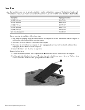
...outlet and then unplugging the AC adapter from the computer. 4. Remove the hard drive: 1. Shut down through the operating system. 2. Removal and replacement procedures 4-10 Disconnect all external devices connected to the computer. 2. The hard drive cover is off or in Hibernation, turn the computer on ...page 4-7). Loosen the two Phillips PM2.5×6.0 captive screws 1 that secure the hard drive cover to the computer. 3. Remove the battery (see "Battery" on , and then shut it up and to the left, and remove the cover. Description 120-GB, 5400-rpm 160-GB, 5400...
...outlet and then unplugging the AC adapter from the computer. 4. Remove the hard drive: 1. Shut down through the operating system. 2. Removal and replacement procedures 4-10 Disconnect all external devices connected to the computer. 2. The hard drive cover is off or in Hibernation, turn the computer on ...page 4-7). Loosen the two Phillips PM2.5×6.0 captive screws 1 that secure the hard drive cover to the computer. 3. Remove the battery (see "Battery" on , and then shut it up and to the left, and remove the cover. Description 120-GB, 5400-rpm 160-GB, 5400...
Service Guide
Page 53
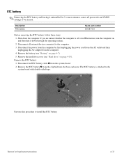
...whether the computer is attached to the computer. 3. Removal and replacement procedures 4-12 Shut down through the operating system. 2. Remove the RTC battery: 1. Description RTC battery Spare part number 501587-001 Before removing the RTC battery, follow these steps: 1. Disconnect the power from the computer ...clip built into the base enclosure. Reverse this procedure to be cleared. RTC battery ✎ Removing the RTC battery and leaving it down the computer. Remove the hard drive cover (see "Battery" on , and then shut it uninstalled for 5 or more minutes causes...
...whether the computer is attached to the computer. 3. Removal and replacement procedures 4-12 Shut down through the operating system. 2. Remove the RTC battery: 1. Description RTC battery Spare part number 501587-001 Before removing the RTC battery, follow these steps: 1. Disconnect the power from the computer ...clip built into the base enclosure. Reverse this procedure to be cleared. RTC battery ✎ Removing the RTC battery and leaving it down the computer. Remove the hard drive cover (see "Battery" on , and then shut it uninstalled for 5 or more minutes causes...


