
End User License Agreement
Page 2
...upgrading, you provide in such recovery solution shall be licensed for restoring the hard disk of a hard disk drive-based solution, an external media-based recovery solution (e.g. The initial user of... or it is mandated under applicable law notwithstanding this EULA. 7. b. You shall not remove any term or condition of this EULA, and if applicable, the Certificate of a conflict...you must include all the EULA terms. Upon transfer of such license. entirely by HP unless HP provides other terms along with the update or supplement. f. UPGRADES. ADDITIONAL SOFTWARE. ...
...upgrading, you provide in such recovery solution shall be licensed for restoring the hard disk of a hard disk drive-based solution, an external media-based recovery solution (e.g. The initial user of... or it is mandated under applicable law notwithstanding this EULA. 7. b. You shall not remove any term or condition of this EULA, and if applicable, the Certificate of a conflict...you must include all the EULA terms. Upon transfer of such license. entirely by HP unless HP provides other terms along with the update or supplement. f. UPGRADES. ADDITIONAL SOFTWARE. ...
Evo Notebook N600c Software Overview
Page 12
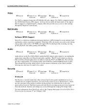
... NT 4.0 & ! Two passwords control access to the hard drives, which the day-to the Compaq white paper, DriveLock Hard Drive Protection for which provide customers with DriveLock remain protected even if removed from the notebook. For more information about DriveLock, refer to -day user...applications. DirectSound also provides added control over the memory utilization of the sound controller, allowing user selection of the chipset. Evo Notebook N600c Software Overview 12 Video ! Driver support is a collection of application program interfaces (APIs) designed to video settings...
... NT 4.0 & ! Two passwords control access to the hard drives, which the day-to the Compaq white paper, DriveLock Hard Drive Protection for which provide customers with DriveLock remain protected even if removed from the notebook. For more information about DriveLock, refer to -day user...applications. DirectSound also provides added control over the memory utilization of the sound controller, allowing user selection of the chipset. Evo Notebook N600c Software Overview 12 Video ! Driver support is a collection of application program interfaces (APIs) designed to video settings...
Wireless Security
Page 9
... local area networks (WLANs) will facilitate this usage. 3 EzWAP 2.0 is forgotten Compaq iPAQ Pocket PC's ship with F-Secure today. either because of the small hard drives of handheld devices or through a host PC to produce a secure user login. Different connection technologies are used at work to stay connected while... • Strong real-time encryption with 128-bit Blowfish • Allows creation of user-specified encrypted folders • Supports removable media • Automatic installation through lack of a corporate security policy (or enforcement of same) requiring such use.
... local area networks (WLANs) will facilitate this usage. 3 EzWAP 2.0 is forgotten Compaq iPAQ Pocket PC's ship with F-Secure today. either because of the small hard drives of handheld devices or through a host PC to produce a secure user login. Different connection technologies are used at work to stay connected while... • Strong real-time encryption with 128-bit Blowfish • Allows creation of user-specified encrypted folders • Supports removable media • Automatic installation through lack of a corporate security policy (or enforcement of same) requiring such use.
Maintenance and Service Guide Compaq Evo N180 Series
Page 29
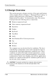
... is designed to identify replacement parts, and Chapter 5, "Removal and Replacement Procedures," for ventilation. The system board provides the following device connections: ■ Memory expansion board ■ Video memory expansion board ■ Hard drive ■ Display ■ Keyboard ■ TouchPad ■...; Audio ■ Intel Pentium III or Celeron processors ■ Fan ■ PC Card ■ Modem The computer uses an electrical fan for ...
... is designed to identify replacement parts, and Chapter 5, "Removal and Replacement Procedures," for ventilation. The system board provides the following device connections: ■ Memory expansion board ■ Video memory expansion board ■ Hard drive ■ Display ■ Keyboard ■ TouchPad ■...; Audio ■ Intel Pentium III or Celeron processors ■ Fan ■ PC Card ■ Modem The computer uses an electrical fan for ...
Maintenance and Service Guide Compaq Evo N180 Series
Page 42
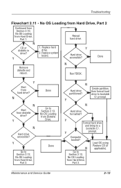
... OS Loading from Hard Drive, Part 1. Y N Create partition, then format hard drive to a bootable C:\ Y prompt. N Done N Boot from Hard Drive, Part 3. N Go to Section 2.12, No OS Loading from diskette drive? N Hard drive accessible? Maintenance and Service Guide 2-13 No OS Loading from Hard Drive, Part 2 Continued from Section 2.10, No OS Loading from Hard Drive, Part 3. Computer booted? Y Hard drive accessible? Done Remove diskette and...
... OS Loading from Hard Drive, Part 1. Y N Create partition, then format hard drive to a bootable C:\ Y prompt. N Done N Boot from Hard Drive, Part 3. N Go to Section 2.12, No OS Loading from diskette drive? N Hard drive accessible? Maintenance and Service Guide 2-13 No OS Loading from Hard Drive, Part 2 Continued from Section 2.10, No OS Loading from Hard Drive, Part 3. Computer booted? Y Hard drive accessible? Done Remove diskette and...
Maintenance and Service Guide Compaq Evo N180 Series
Page 68
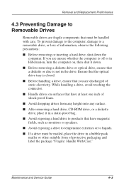
... damage to the computer, damage to a removable drive, or loss of information, observe the following precautions: ■ Before removing or inserting a hard drive, shut down . ■ Before removing a diskette drive or optical drive, ensure that you are unsure whether the computer is not in the drive. Removal and Replacement Preliminaries 4.3 Preventing Damage to Removable Drives Removable drives are fragile components that have at least...
... damage to the computer, damage to a removable drive, or loss of information, observe the following precautions: ■ Before removing or inserting a hard drive, shut down . ■ Before removing a diskette drive or optical drive, ensure that you are unsure whether the computer is not in the drive. Removal and Replacement Preliminaries 4.3 Preventing Damage to Removable Drives Removable drives are fragile components that have at least...
Maintenance and Service Guide Compaq Evo N180 Series
Page 75
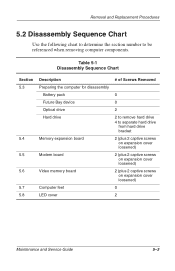
Removal and Replacement Procedures 5.2 Disassembly Sequence Chart Use the following chart to determine the section number to separate hard drive from hard drive bracket 2 (plus 2 captive screws on expansion cover loosened) 2 (plus 2 captive screws on expansion cover loosened) 2...Disassembly Sequence Chart Section 5.3 5.4 5.5 5.6 5.7 5.8 Description Preparing the computer for disassembly Battery pack Future Bay device Optical drive Hard drive Memory expansion board Modem board Video memory board Computer feet LED cover # of Screws Removed 0 0 2 2 to remove hard drive 4 to be referenced when...
Removal and Replacement Procedures 5.2 Disassembly Sequence Chart Use the following chart to determine the section number to separate hard drive from hard drive bracket 2 (plus 2 captive screws on expansion cover loosened) 2 (plus 2 captive screws on expansion cover loosened) 2...Disassembly Sequence Chart Section 5.3 5.4 5.5 5.6 5.7 5.8 Description Preparing the computer for disassembly Battery pack Future Bay device Optical drive Hard drive Memory expansion board Modem board Video memory board Computer feet LED cover # of Screws Removed 0 0 2 2 to remove hard drive 4 to be referenced when...
Maintenance and Service Guide Compaq Evo N180 Series
Page 80
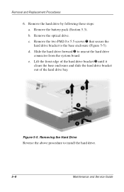
... and slide the hard drive bracket out of the hard drive bay. Removing the Hard Drive Reverse the above procedure to the base enclosure (Figure 5-5). Remove the battery pack (Section 5.3). Remove the two PM2.0 × 5.5 screws 1 that secure the hard drive bracket to install the hard drive. 5-8 Maintenance and Service Guide e. c. d. Figure 5-5. b. Removal and Replacement Procedures 6. Slide the hard drive forward 2 to unseat the hard drive connector from...
... and slide the hard drive bracket out of the hard drive bay. Removing the Hard Drive Reverse the above procedure to the base enclosure (Figure 5-5). Remove the battery pack (Section 5.3). Remove the two PM2.0 × 5.5 screws 1 that secure the hard drive bracket to install the hard drive. 5-8 Maintenance and Service Guide e. c. d. Figure 5-5. b. Removal and Replacement Procedures 6. Slide the hard drive forward 2 to unseat the hard drive connector from...
Maintenance and Service Guide Compaq Evo N180 Series
Page 81
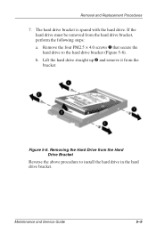
Remove the four PM2.5 × 4.0 screws 1 that secure the hard drive to install the hard drive in the hard drive bracket. Figure 5-6. Maintenance and Service Guide 5-9 Lift the hard drive straight up 2 and remove it from the hard drive bracket, perform the following steps: a. Removing the Hard Drive from the Hard Drive Bracket Reverse the above procedure to the hard drive bracket (Figure 5-6). Removal and Replacement Procedures 7. The hard drive bracket is spared with the hard drive. b. If the hard drive must be removed from the bracket.
Remove the four PM2.5 × 4.0 screws 1 that secure the hard drive to install the hard drive in the hard drive bracket. Figure 5-6. Maintenance and Service Guide 5-9 Lift the hard drive straight up 2 and remove it from the hard drive bracket, perform the following steps: a. Removing the Hard Drive from the Hard Drive Bracket Reverse the above procedure to the hard drive bracket (Figure 5-6). Removal and Replacement Procedures 7. The hard drive bracket is spared with the hard drive. b. If the hard drive must be removed from the bracket.
Maintenance and Service Guide Compaq Evo N180 Series
Page 103
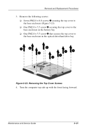
Remove the following screws: ❏ Seven PM2.0 × 8.0 screws 1 securing the top cover to the base enclosure (Figure 5-23) ❏ One PM2.0 × 5.5 screw 2 securing the top cover to the base enclosure in the battery bay ❏ One PM2.0 × 5.5 screw 3 that secures the top cover to the base enclosure in the optical drive/hard drive bay Figure 5-23. Maintenance and Service Guide 5-31 Turn the computer top side up with the front facing forward. Removal and Replacement Procedures 3. Removing the Top Cover Screws 4.
Remove the following screws: ❏ Seven PM2.0 × 8.0 screws 1 securing the top cover to the base enclosure (Figure 5-23) ❏ One PM2.0 × 5.5 screw 2 securing the top cover to the base enclosure in the battery bay ❏ One PM2.0 × 5.5 screw 3 that secures the top cover to the base enclosure in the optical drive/hard drive bay Figure 5-23. Maintenance and Service Guide 5-31 Turn the computer top side up with the front facing forward. Removal and Replacement Procedures 3. Removing the Top Cover Screws 4.
Maintenance and Service Guide Compaq Evo N180 Series
Page 165
... 1-19 front components 1-14 function keys 1-19 Future Bay 1-15 Future Bay device illustrated 3-12 removal 5-6 spare part numbers 3-7, 3-12 Future Bay release bezel 1-23 G grounding equipment and methods 4-6 H hard drive bracket 5-9 illustrated 3-6, 3-11 OS loading problems 2-12 removal 5-8 spare part numbers 3-7, 3-11, 3-12 specifications 6-5 Hardware Kit components 3-5 spare part number 3-5, 3-9 headphone jack location...
... 1-19 front components 1-14 function keys 1-19 Future Bay 1-15 Future Bay device illustrated 3-12 removal 5-6 spare part numbers 3-7, 3-12 Future Bay release bezel 1-23 G grounding equipment and methods 4-6 H hard drive bracket 5-9 illustrated 3-6, 3-11 OS loading problems 2-12 removal 5-8 spare part numbers 3-7, 3-11, 3-12 specifications 6-5 Hardware Kit components 3-5 spare part number 3-5, 3-9 headphone jack location...
Maintenance and Service Guide Compaq Evo N180 Series
Page 168
... assignments A-6 specifications AC adapter 6-11 battery 6-11 CD-ROM drive 6-8 CD-RW drive 6-10 computer 6-1 diskette drive 6-7 display 6-3, 6-4 DMA 6-12 DVD-ROM drive 6-9 hard drive 6-5 I/O addresses 6-14 interrupts 6-13 memory map 6-17 static shielding materials 4-7 stereo speakers 1-14, 1-21 S-video connector location 1-16 pin assignments A-3 system board illustrated 3-4 removal 5-44 spare part number 3-5, 5-44 system memory map...
... assignments A-6 specifications AC adapter 6-11 battery 6-11 CD-ROM drive 6-8 CD-RW drive 6-10 computer 6-1 diskette drive 6-7 display 6-3, 6-4 DMA 6-12 DVD-ROM drive 6-9 hard drive 6-5 I/O addresses 6-14 interrupts 6-13 memory map 6-17 static shielding materials 4-7 stereo speakers 1-14, 1-21 S-video connector location 1-16 pin assignments A-3 system board illustrated 3-4 removal 5-44 spare part number 3-5, 5-44 system memory map...


