
Evo Notebook N600c Software Overview
Page 9
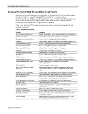
...Easy Access Buttons Software Easy Point IV Hot Key Support Insight Management Agents Insight Management Web Agents ESS Audio Driver Mini PCI Communications Support and Drivers MultiBay Plug and Play Manager Netflex-3 Ethernet Drivers Power Management Power Management Enhancements ATI Video ...Enables internal modem and modem/NIC combination devices and supports Intel PCI NIC that are currently available. Table 5. SoftPaqs provide a distribution method for driver and ROM updates and product software enhancements. Evo Notebook N600c Software Overview 9 Compaq Worldwide Web Site and Download ...
...Easy Access Buttons Software Easy Point IV Hot Key Support Insight Management Agents Insight Management Web Agents ESS Audio Driver Mini PCI Communications Support and Drivers MultiBay Plug and Play Manager Netflex-3 Ethernet Drivers Power Management Power Management Enhancements ATI Video ...Enables internal modem and modem/NIC combination devices and supports Intel PCI NIC that are currently available. Table 5. SoftPaqs provide a distribution method for driver and ROM updates and product software enhancements. Evo Notebook N600c Software Overview 9 Compaq Worldwide Web Site and Download ...

Maintenance and Service Guide
Page 4
... 4-5 4.7 Grounding Equipment and Methods 4-6 5 Removal and Replacement Procedures 5.1 Serial Number 5-2 5.2 Disassembly Sequence Chart 5-3 5.3 Preparing the Computer for Disassembly 5-4 5.4 Computer Feet 5-13 5.5 Memory Expansion Board 5-13 5.6 Mini PCI Communications Board 5-15 5.7 Disk Cell RTC Battery 5-18 5.8 Connector Cover 5-19 5.9 LED Cover 5-20 5.10 Keyboard 5-22 5.11 Heat Spreader 5-25 5.12 Processor 5-28 5.13...
... 4-5 4.7 Grounding Equipment and Methods 4-6 5 Removal and Replacement Procedures 5.1 Serial Number 5-2 5.2 Disassembly Sequence Chart 5-3 5.3 Preparing the Computer for Disassembly 5-4 5.4 Computer Feet 5-13 5.5 Memory Expansion Board 5-13 5.6 Mini PCI Communications Board 5-15 5.7 Disk Cell RTC Battery 5-18 5.8 Connector Cover 5-19 5.9 LED Cover 5-20 5.10 Keyboard 5-22 5.11 Heat Spreader 5-25 5.12 Processor 5-28 5.13...

Maintenance and Service Guide
Page 32
Evo Notebook N1020v and N1000v models only) ■ Network interface card (NIC) integrated on the system board, with a mini PCI V.92 modem ■ Integrated wireless support of shared Synchronous DRAM (SDRAM) and 4X AGP graphics card ■ 128-MB ... with support for both 32-bit CardBus and 16-bit PC Cards ■ External 65 W AC adapter with : ❏ TouchPad pointing device (Evo Notebook N1020v and N1000v and Presario 1500 models) ❏ Dual Stick (TouchPad and point stick; Product Description ❏ The Evo Notebook N1000v features an Intel Mobile Pentium 4 2.2-, 2.0-, 1.8-, ...
Evo Notebook N1020v and N1000v models only) ■ Network interface card (NIC) integrated on the system board, with a mini PCI V.92 modem ■ Integrated wireless support of shared Synchronous DRAM (SDRAM) and 4X AGP graphics card ■ 128-MB ... with support for both 32-bit CardBus and 16-bit PC Cards ■ External 65 W AC adapter with : ❏ TouchPad pointing device (Evo Notebook N1020v and N1000v and Presario 1500 models) ❏ Dual Stick (TouchPad and point stick; Product Description ❏ The Evo Notebook N1000v features an Intel Mobile Pentium 4 2.2-, 2.0-, 1.8-, ...
Maintenance and Service Guide
Page 44
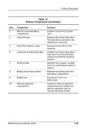
.... Secures the hard drive to be entered before using some Windows operating systems. Identifies the computer; Product Description Table 1-9 Bottom Components (Continued) Item 3 4 5 6 7 8 9 10 Component Mini PCI communications compartment Hard drive bay Hard drive retention screw Certificate of Authenticity label Serial number Battery pack release switch Battery bay Memory expansion compartment Function...
.... Secures the hard drive to be entered before using some Windows operating systems. Identifies the computer; Product Description Table 1-9 Bottom Components (Continued) Item 3 4 5 6 7 8 9 10 Component Mini PCI communications compartment Hard drive bay Hard drive retention screw Certificate of Authenticity label Serial number Battery pack release switch Battery bay Memory expansion compartment Function...
Maintenance and Service Guide
Page 80
... shield Optical drive rear alignment rail Optical drive front alignment rail PC Card space saver *Connector cover *Hard drive bracket *Mini PCI compartment cover *Memory expansion compartment cover *Battery bezel *Includes two of each part, one with carbon finish for use with Evo Notebook N1020v and N1000v models and one with silver finish for use with...
... shield Optical drive rear alignment rail Optical drive front alignment rail PC Card space saver *Connector cover *Hard drive bracket *Mini PCI compartment cover *Memory expansion compartment cover *Battery bezel *Includes two of each part, one with carbon finish for use with Evo Notebook N1020v and N1000v models and one with silver finish for use with...

Maintenance and Service Guide
Page 92
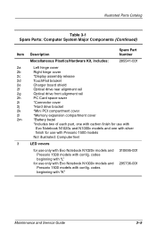
...drive 24X Max DVD-ROM/CD-RW combination drive 8X Max DVD-ROM/CD-RW combination drive for use only with Evo Notebook N1000v models and Presario 1500 models with config. codes beginning with config. modem International modem Disk cell RTC battery,..., 62 Wh, 4.0 Ah, Li ion 8 cell, 58 Wh, 3.6 Ah, Li ion Optical drives for use only with Evo Notebook N1020v models and Presario 1500 models with "K" 24X Max CD-ROM drive 8X Max DVD-ROM drive 24X Max DVD-ROM/CD-RW...3-1 Spare Parts: Computer System Major Components (Continued) Item 18 19 20 21 22 Description Mini PCI communications boards U.S.
...drive 24X Max DVD-ROM/CD-RW combination drive 8X Max DVD-ROM/CD-RW combination drive for use only with Evo Notebook N1000v models and Presario 1500 models with config. codes beginning with config. modem International modem Disk cell RTC battery,..., 62 Wh, 4.0 Ah, Li ion 8 cell, 58 Wh, 3.6 Ah, Li ion Optical drives for use only with Evo Notebook N1020v models and Presario 1500 models with "K" 24X Max CD-ROM drive 8X Max DVD-ROM drive 24X Max DVD-ROM/CD-RW...3-1 Spare Parts: Computer System Major Components (Continued) Item 18 19 20 21 22 Description Mini PCI communications boards U.S.
Maintenance and Service Guide
Page 94
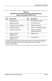
...Number 285541-001 Item Description Item Description 1 Left hinge cover 8 PC Card space saver 2 Right hinge cover 9 *Connector cover 3 *Display release assembly 10 *Hard drive bracket 4 TouchPad bracket 11 *Mini PCI compartment cover 5 Charger board shield 12 *Memory expansion compartment cover ...6 Optical drive rear alignment rail 13 *Battery bezel 7 Optical drive front alignment rail 14 Computer feet *Includes two of each part, one with carbon finish for use with Evo Notebook N1020v and...
...Number 285541-001 Item Description Item Description 1 Left hinge cover 8 PC Card space saver 2 Right hinge cover 9 *Connector cover 3 *Display release assembly 10 *Hard drive bracket 4 TouchPad bracket 11 *Mini PCI compartment cover 5 Charger board shield 12 *Memory expansion compartment cover ...6 Optical drive rear alignment rail 13 *Battery bezel 7 Optical drive front alignment rail 14 Computer feet *Includes two of each part, one with carbon finish for use with Evo Notebook N1020v and...

Maintenance and Service Guide
Page 109
... 5.11 5.12 5.13 5.14 5.15 Disassembly Sequence Chart Description Preparing the computer for disassembly Battery pack Optical drive Hard drive Computer feet Memory expansion board Mini PCI communications board Disk cell RTC battery Connector cover LED cover Keyboard Heat spreader Processor Display Palm rest Diskette drive # of Screws Removed 0 2 1 to remove the...
... 5.11 5.12 5.13 5.14 5.15 Disassembly Sequence Chart Description Preparing the computer for disassembly Battery pack Optical drive Hard drive Computer feet Memory expansion board Mini PCI communications board Disk cell RTC battery Connector cover LED cover Keyboard Heat spreader Processor Display Palm rest Diskette drive # of Screws Removed 0 2 1 to remove the...

Maintenance and Service Guide
Page 121
The board tilts up at a 45-degree angle 2. Removing a Memory Expansion Board Reverse the preceding procedures to release the memory expansion board. Figure 5-11. modem International modem 248776-001 285545-001 Maintenance and Service Guide 5-15 Removal and Replacement Procedures 7. Spread the memory expansion slot retaining tabs 1 to install a memory expansion board. 5.6 Mini PCI Communications Board Mini PCI Communication Boards Spare Part Number Information U.S. Remove the board by pulling it away from the connector at a 45-degree angle (Figure 5-11). 8.
The board tilts up at a 45-degree angle 2. Removing a Memory Expansion Board Reverse the preceding procedures to release the memory expansion board. Figure 5-11. modem International modem 248776-001 285545-001 Maintenance and Service Guide 5-15 Removal and Replacement Procedures 7. Spread the memory expansion slot retaining tabs 1 to install a memory expansion board. 5.6 Mini PCI Communications Board Mini PCI Communication Boards Spare Part Number Information U.S. Remove the board by pulling it away from the connector at a 45-degree angle (Figure 5-11). 8.

Maintenance and Service Guide
Page 122
....5 × 4.0 screw 1 that secures the mini PCI compartment cover to the left edge of the cover and swing it to the right 3. 6. Figure 5-12. Slide the cover to the base enclosure (Figure 5-12). 4. Lift the left 2. 5. Turn the computer bottom side up with carbon finish for Evo Notebook N1020v and N1000v models and silver finish...
....5 × 4.0 screw 1 that secures the mini PCI compartment cover to the left edge of the cover and swing it to the right 3. 6. Figure 5-12. Slide the cover to the base enclosure (Figure 5-12). 4. Lift the left 2. 5. Turn the computer bottom side up with carbon finish for Evo Notebook N1020v and N1000v models and silver finish...

Maintenance and Service Guide
Page 123
The board releases and rests at an angle 3. Removing a Mini PCI Communications Board Reverse the preceding procedures to install a mini PCI communications board. Maintenance and Service Guide 5-17 Remove the board by pulling it away from the mini PCI communications board 1 (Figure 5-13). 8. Figure 5-13. Removal and Replacement Procedures 7. Spread the retaining tabs 2 on each side of the mini PCI communications board. Disconnect the modem cable from the socket at an angle. 9.
The board releases and rests at an angle 3. Removing a Mini PCI Communications Board Reverse the preceding procedures to install a mini PCI communications board. Maintenance and Service Guide 5-17 Remove the board by pulling it away from the mini PCI communications board 1 (Figure 5-13). 8. Figure 5-13. Removal and Replacement Procedures 7. Spread the retaining tabs 2 on each side of the mini PCI communications board. Disconnect the modem cable from the socket at an angle. 9.

Maintenance and Service Guide
Page 124
Removal and Replacement Procedures 5.7 Disk Cell RTC Battery Disk Cell RTC Battery Spare Part Number Information Disk cell RTC battery 279769-001 1. Remove the RTC battery from its socket on the system board (Figure 5-14). Removing the Disk Cell RTC Battery ✎ The computer uses a CR1220 lithium disk cell battery. Remove the mini PCI compartment cover (Section 5.6). 3. When replacing the RTC battery, insert the battery with the "+" sign facing up. 5-18 Maintenance and Service Guide Figure 5-14. Prepare the computer for disassembly (Section 5.3). 2.
Removal and Replacement Procedures 5.7 Disk Cell RTC Battery Disk Cell RTC Battery Spare Part Number Information Disk cell RTC battery 279769-001 1. Remove the RTC battery from its socket on the system board (Figure 5-14). Removing the Disk Cell RTC Battery ✎ The computer uses a CR1220 lithium disk cell battery. Remove the mini PCI compartment cover (Section 5.6). 3. When replacing the RTC battery, insert the battery with the "+" sign facing up. 5-18 Maintenance and Service Guide Figure 5-14. Prepare the computer for disassembly (Section 5.3). 2.

Maintenance and Service Guide
Page 162
Prepare the computer for use only with Evo Notebook N1020v models and Presario 1500 models with "K" 311282-001 285515-001 ✎ When replacing the system board, ensure that the following components: a. Keyboard (Section 5.10)... not contain memory) for use only with Evo Notebook N1000v models and Presario 1500 models with "L" for disassembly (Section 5.3) and remove the following components are removed from the old system board and installed on the new system board: ■ Memory expansion boards (Section 5.5) ■ Mini PCI communications board (Section 5.6) ■ Disk cell...
Prepare the computer for use only with Evo Notebook N1020v models and Presario 1500 models with "K" 311282-001 285515-001 ✎ When replacing the system board, ensure that the following components: a. Keyboard (Section 5.10)... not contain memory) for use only with Evo Notebook N1000v models and Presario 1500 models with "L" for disassembly (Section 5.3) and remove the following components are removed from the old system board and installed on the new system board: ■ Memory expansion boards (Section 5.5) ■ Mini PCI communications board (Section 5.6) ■ Disk cell...

Maintenance and Service Guide
Page 209
PM2.5 × 4.0 Screw Locations Maintenance and Service Guide C-13 Table C-4 Phillips Metric 2.5 × 4.0 Screw Head Color Qty Length Thread Width Silver 2 4.0 mm 2.5 mm 5.0 mm Where used: 1 One screw that secures the memory expansion compartment cover to the base enclosure (documented in Section 5.5) 2 One screw that secures the mini PCI compartment cover to the base enclosure (documented in Section 5.6) Figure C-12.
PM2.5 × 4.0 Screw Locations Maintenance and Service Guide C-13 Table C-4 Phillips Metric 2.5 × 4.0 Screw Head Color Qty Length Thread Width Silver 2 4.0 mm 2.5 mm 5.0 mm Where used: 1 One screw that secures the memory expansion compartment cover to the base enclosure (documented in Section 5.5) 2 One screw that secures the mini PCI compartment cover to the base enclosure (documented in Section 5.6) Figure C-12.

Maintenance and Service Guide
Page 216
... illustrated 3-18 removal 5-14 memory map specifications 6-20 microphone 1-38 illustrated 3-20 removal 5-52 microphone jack location 1-33 pin assignments A-6 mini PCI board removal 5-15 spare part numbers 3-17, 5-15 mini PCI compartment 1-40 mini PCI compartment cover illustrated 3-18 removal 5-16 Miscellaneous Cable Kit components 3-20 spare part number 3-9, 3-21 Miscellaneous Plastics/Hardware Kit components...
... illustrated 3-18 removal 5-14 memory map specifications 6-20 microphone 1-38 illustrated 3-20 removal 5-52 microphone jack location 1-33 pin assignments A-6 mini PCI board removal 5-15 spare part numbers 3-17, 5-15 mini PCI compartment 1-40 mini PCI compartment cover illustrated 3-18 removal 5-16 Miscellaneous Cable Kit components 3-20 spare part number 3-9, 3-21 Miscellaneous Plastics/Hardware Kit components...


