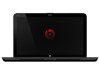
HP ENVY 15 - Maintenance and Service Guide
Page 4
... 4 Removal and replacement procedures Preliminary replacement requirements 4-1 Tools required 4-1 Service considerations 4-1 Grounding guidelines 4-2 Service tag 4-5 Component replacement procedures 4-6 Computer feet 4-6 Battery 4-7 Expansion memory module 4-8 Top cover 4-10 Keyboard 4-12 Speaker assembly 4-14 Primary memory module 4-15 WLAN module 4-16 RTC battery 4-19 Hard drive 4-20 Maintenance and Service Guide iv
... 4 Removal and replacement procedures Preliminary replacement requirements 4-1 Tools required 4-1 Service considerations 4-1 Grounding guidelines 4-2 Service tag 4-5 Component replacement procedures 4-6 Computer feet 4-6 Battery 4-7 Expansion memory module 4-8 Top cover 4-10 Keyboard 4-12 Speaker assembly 4-14 Primary memory module 4-15 WLAN module 4-16 RTC battery 4-19 Hard drive 4-20 Maintenance and Service Guide iv
HP ENVY 15 - Maintenance and Service Guide
Page 24
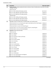
...antenna transceivers and cables, nameplate, and logo): With bronze finish: ■ 15.6-in, WVA, AntiGlare LED display assembly 591172-001 ■ 15.6-in, WVA, BrightView LED display assembly 576803-001 ■ 15.6-in, SVA, BrightView LED display assembly 576802-001 With black finish: &#...9632; 15.6-in, WVA, AntiGlare LED display assembly 591173-001 ■ 15.6-in, WVA, BrightView LED display assembly 580127-001 ■ 15.6-in, SVA, BrightView LED display assembly 580126-001 Top cover (includes TouchPad board, TouchPad bracket, and TouchPad...
...antenna transceivers and cables, nameplate, and logo): With bronze finish: ■ 15.6-in, WVA, AntiGlare LED display assembly 591172-001 ■ 15.6-in, WVA, BrightView LED display assembly 576803-001 ■ 15.6-in, SVA, BrightView LED display assembly 576802-001 With black finish: &#...9632; 15.6-in, WVA, AntiGlare LED display assembly 591173-001 ■ 15.6-in, WVA, BrightView LED display assembly 580127-001 ■ 15.6-in, SVA, BrightView LED display assembly 580126-001 Top cover (includes TouchPad board, TouchPad bracket, and TouchPad...
HP ENVY 15 - Maintenance and Service Guide
Page 28
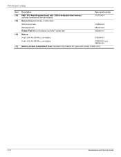
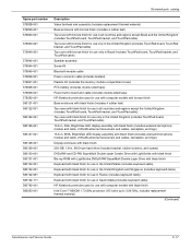
Illustrated parts catalog Item (14) (15) (16) (17) Description Spare part number PM57 PCH Peak-M system board with 1 GB of dedicated video memory (includes replacement thermal material) 576772-001 Base enclosure (..., 2.80-Ah (93-Wh) Li-ion battery 576834-001 6-cell, 2.40-Ah (53-Wh) Li-ion battery 576833-001 and 586025-001 Memory module compartment cover (included in the Plastics Kit, spare part number 576847-001) 3-8 Maintenance and Service Guide
Illustrated parts catalog Item (14) (15) (16) (17) Description Spare part number PM57 PCH Peak-M system board with 1 GB of dedicated video memory (includes replacement thermal material) 576772-001 Base enclosure (..., 2.80-Ah (93-Wh) Li-ion battery 576834-001 6-cell, 2.40-Ah (53-Wh) Li-ion battery 576833-001 and 586025-001 Memory module compartment cover (included in the Plastics Kit, spare part number 576847-001) 3-8 Maintenance and Service Guide
HP ENVY 15 - Maintenance and Service Guide
Page 37
...cable Power connector cable (includes bracket) Plastics Kit (includes the memory module compartment cover) RTC battery (includes double-sided tape) Power button board and cable (includes double-sided tape) HP Notebook protective case for use with computer models with bronze finish Base enclosure with ...LED display assembly with black finish (includes webcam/microphone module and cable, 2 WLAN antenna transceivers and cables, nameplate, and logo) 15.6-in, WVA, BrightView LED display assembly with black finish (includes webcam/microphone module and cable, 2 WLAN antenna transceivers and cables, ...
...cable Power connector cable (includes bracket) Plastics Kit (includes the memory module compartment cover) RTC battery (includes double-sided tape) Power button board and cable (includes double-sided tape) HP Notebook protective case for use with computer models with bronze finish Base enclosure with ...LED display assembly with black finish (includes webcam/microphone module and cable, 2 WLAN antenna transceivers and cables, nameplate, and logo) 15.6-in, WVA, BrightView LED display assembly with black finish (includes webcam/microphone module and cable, 2 WLAN antenna transceivers and cables, ...
HP ENVY 15 - Maintenance and Service Guide
Page 40
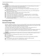
..., avoid touching the connector. ■ Before removing a diskette drive or optical drive, be sure that a diskette or disc is closed. ■ Handle drives on surfaces covered with care. Networks built into many cases, ESD contains enough power to electrostatic discharge (ESD). Grounding guidelines Electrostatic discharge damage Electronic components are sensitive to...
..., avoid touching the connector. ■ Before removing a diskette drive or optical drive, be sure that a diskette or disc is closed. ■ Handle drives on surfaces covered with care. Networks built into many cases, ESD contains enough power to electrostatic discharge (ESD). Grounding guidelines Electrostatic discharge damage Electronic components are sensitive to...
HP ENVY 15 - Maintenance and Service Guide
Page 42
... antistatic bags and floor mats. Foot straps (heel, toe, or boot straps) can be worn in the ground cords. Handle these workstation grounding guidelines: ■ Cover the workstation with the skin. To provide proper ground, wear a strap snugly against the skin at standing workstations and are flexible straps with a minimum of...
... antistatic bags and floor mats. Foot straps (heel, toe, or boot straps) can be worn in the ground cords. Handle these workstation grounding guidelines: ■ Cover the workstation with the skin. To provide proper ground, wear a strap snugly against the skin at standing workstations and are flexible straps with a minimum of...
HP ENVY 15 - Maintenance and Service Guide
Page 46
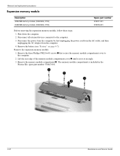
... adapter from the computer. 4. Remove the three Phillips PM2.0×4.0 screws 1 that secure the memory module compartment cover to the computer. 3. Remove the expansion memory module: 1. Lift the rear edge of the memory module compartment cover 2 until it rests at an angle. 3. Shut down the computer. 2. The memory module compartment is included...
... adapter from the computer. 4. Remove the three Phillips PM2.0×4.0 screws 1 that secure the memory module compartment cover to the computer. 3. Remove the expansion memory module: 1. Lift the rear edge of the memory module compartment cover 2 until it rests at an angle. 3. Shut down the computer. 2. The memory module compartment is included...
HP ENVY 15 - Maintenance and Service Guide
Page 48
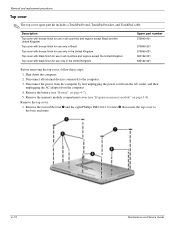
...see "Expansion memory module" on page 4-7). 5. Remove the four rubber feet 1 and the eight Phillips PM2.0×12.0 screws 2 that secure the top cover to the computer. 3. Disconnect the power from the computer by first unplugging the power cord from the AC outlet, and then unplugging the AC adapter... from the computer. 4. Remove the top cover: 1. Disconnect all countries and regions except the United Kingdom Top cover with black finish for use in the United Kingdom Spare part number 576840-001 576840-201 576840-031 580122-...
...see "Expansion memory module" on page 4-7). 5. Remove the four rubber feet 1 and the eight Phillips PM2.0×12.0 screws 2 that secure the top cover to the computer. 3. Disconnect the power from the computer by first unplugging the power cord from the AC outlet, and then unplugging the AC adapter... from the computer. 4. Remove the top cover: 1. Disconnect all countries and regions except the United Kingdom Top cover with black finish for use in the United Kingdom Spare part number 576840-001 576840-201 576840-031 580122-...
HP ENVY 15 - Maintenance and Service Guide
Page 49
...the TouchPad cable 3 from the system board. 6. Release the zero insertion force (ZIF) connector to the base enclosure. 3. Release the top cover by lifting the front edge 1 until it rests at an angle. 5. Maintenance and Service Guide 4-11 Remove the two Phillips PM2.0×5.0 ...screws 1 and the four Phillips PM2.0×2.0 screws 2 that secure the top cover to which the keyboard cable is attached, and then disconnect the keyboard cable 4 from the system board. 8. Disconnect the LED board cable 2 from...
...the TouchPad cable 3 from the system board. 6. Release the zero insertion force (ZIF) connector to the base enclosure. 3. Release the top cover by lifting the front edge 1 until it rests at an angle. 5. Maintenance and Service Guide 4-11 Remove the two Phillips PM2.0×5.0 ...screws 1 and the four Phillips PM2.0×2.0 screws 2 that secure the top cover to which the keyboard cable is attached, and then disconnect the keyboard cable 4 from the system board. 8. Disconnect the LED board cable 2 from...
HP ENVY 15 - Maintenance and Service Guide
Page 50
... AC outlet, and then unplugging the AC adapter from the computer. 4. Remove the memory module compartment cover (see "Battery" on page 4-10). 4-12 Maintenance and Service Guide Shut down the computer. 2. Remove the top cover (see "Top cover" on page 4-7). 5. Disconnect all external devices connected to the computer. 3. Keyboard for use in country...
... AC outlet, and then unplugging the AC adapter from the computer. 4. Remove the memory module compartment cover (see "Battery" on page 4-10). 4-12 Maintenance and Service Guide Shut down the computer. 2. Remove the top cover (see "Top cover" on page 4-7). 5. Disconnect all external devices connected to the computer. 3. Keyboard for use in country...
HP ENVY 15 - Maintenance and Service Guide
Page 51
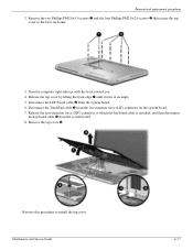
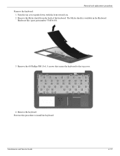
Remove the Mylar shield from the back of the keyboard. Remove the keyboard. Maintenance and Service Guide 4-13 Turn the top cover upside down, with the front toward you. 2. Removal and replacement procedures Remove the keyboard: 1. Reverse this procedure to the top cover. 4. The Mylar shield is available in the Keyboard Hardware Kit, spare part number 576836-001. 3. Remove the 60 Phillips PM1.5×1.5 screws that secure the keyboard to install the keyboard.
Remove the Mylar shield from the back of the keyboard. Remove the keyboard. Maintenance and Service Guide 4-13 Turn the top cover upside down, with the front toward you. 2. Removal and replacement procedures Remove the keyboard: 1. Reverse this procedure to the top cover. 4. The Mylar shield is available in the Keyboard Hardware Kit, spare part number 576836-001. 3. Remove the 60 Phillips PM1.5×1.5 screws that secure the keyboard to install the keyboard.
HP ENVY 15 - Maintenance and Service Guide
Page 52
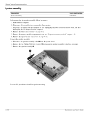
... 2. Remove the two Phillips PM2.0×4.0 screws 2 that secure the speaker assembly to the computer. 3. Remove the memory module compartment cover (see "Battery" on page 4-7). 5. Remove the battery (see "Expansion memory module" on page 4-10). Disconnect the speaker assembly ...the speaker assembly: 1. Reverse this procedure to install the speaker assembly. 4-14 Maintenance and Service Guide Remove the top cover (see "Top cover" on page 4-8). 6. Shut down the computer. 2. Removal and replacement procedures Speaker assembly Description Speaker assembly Spare part number...
... 2. Remove the two Phillips PM2.0×4.0 screws 2 that secure the speaker assembly to the computer. 3. Remove the memory module compartment cover (see "Battery" on page 4-7). 5. Remove the battery (see "Expansion memory module" on page 4-10). Disconnect the speaker assembly ...the speaker assembly: 1. Reverse this procedure to install the speaker assembly. 4-14 Maintenance and Service Guide Remove the top cover (see "Top cover" on page 4-8). 6. Shut down the computer. 2. Removal and replacement procedures Speaker assembly Description Speaker assembly Spare part number...
HP ENVY 15 - Maintenance and Service Guide
Page 53
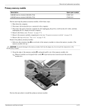
... PC3) Spare part number 576817-001 576816-001 Before removing the primary memory module, follow these steps: 1. Remove the battery (see "Top cover" on page 4-10). Grasp the edge of the memory module 2, and gently pull it by first unplugging the power cord from the AC ... to install the primary memory module. Remove the primary memory module: 1. Reverse this procedure to the computer. 3. Maintenance and Service Guide 4-15 Remove the top cover (see "Battery" on each side of the memory module slot. ✎ Memory modules are designed with a notch 3 to the memory module...
... PC3) Spare part number 576817-001 576816-001 Before removing the primary memory module, follow these steps: 1. Remove the battery (see "Top cover" on page 4-10). Grasp the edge of the memory module 2, and gently pull it by first unplugging the power cord from the AC ... to install the primary memory module. Remove the primary memory module: 1. Reverse this procedure to the computer. 3. Maintenance and Service Guide 4-15 Remove the top cover (see "Battery" on each side of the memory module slot. ✎ Memory modules are designed with a notch 3 to the memory module...
HP ENVY 15 - Maintenance and Service Guide
Page 55
... power cord from the AC outlet, and then unplugging the AC adapter from the computer. 4. Remove the memory module compartment cover (see "Battery" on page 4-10). Remove the top cover (see "Top cover" on page 4-7). 5. Removal and replacement procedures Description Spare part number Intel WiFi Link 5100 802.11 a/b/g WLAN module for use...
... power cord from the AC outlet, and then unplugging the AC adapter from the computer. 4. Remove the memory module compartment cover (see "Battery" on page 4-10). Remove the top cover (see "Top cover" on page 4-7). 5. Removal and replacement procedures Description Spare part number Intel WiFi Link 5100 802.11 a/b/g WLAN module for use...
HP ENVY 15 - Maintenance and Service Guide
Page 57
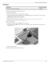
... this procedure to the computer. 3. Maintenance and Service Guide 4-19 Disconnect all external devices connected to install the RTC battery. Remove the memory module compartment cover (see "Battery" on page 4-10). RTC battery Removal and replacement procedures Description RTC battery (includes double-sided tape) Spare part number 576848-001 Before removing... these steps: 1. Shut down the computer. 2. Detach the RTC battery 2 from the computer. 4. Disconnect the RTC battery cable 1 from the system board. 2. Remove the top cover (see "Top cover" on page 4-7). 5.
... this procedure to the computer. 3. Maintenance and Service Guide 4-19 Disconnect all external devices connected to install the RTC battery. Remove the memory module compartment cover (see "Battery" on page 4-10). RTC battery Removal and replacement procedures Description RTC battery (includes double-sided tape) Spare part number 576848-001 Before removing... these steps: 1. Shut down the computer. 2. Detach the RTC battery 2 from the computer. 4. Disconnect the RTC battery cable 1 from the system board. 2. Remove the top cover (see "Top cover" on page 4-7). 5.
HP ENVY 15 - Maintenance and Service Guide
Page 58
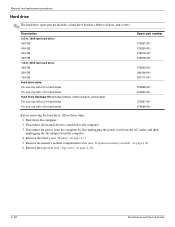
Disconnect all external devices connected to the computer. 3. Remove the battery (see "Top cover" on page 4-10). 4-20 Maintenance and Service Guide Remove the top cover (see "Battery" on page 4-8). 6. Shut down the computer. 2. Removal and replacement procedures Hard drive ✎ The hard drive spare part kit includes a hard drive bracket, ... computer by first unplugging the power cord from the AC outlet, and then unplugging the AC adapter from the computer. 4. Remove the memory module compartment cover (see "Expansion memory module" on page 4-7). 5.
Disconnect all external devices connected to the computer. 3. Remove the battery (see "Top cover" on page 4-10). 4-20 Maintenance and Service Guide Remove the top cover (see "Battery" on page 4-8). 6. Shut down the computer. 2. Removal and replacement procedures Hard drive ✎ The hard drive spare part kit includes a hard drive bracket, ... computer by first unplugging the power cord from the AC outlet, and then unplugging the AC adapter from the computer. 4. Remove the memory module compartment cover (see "Expansion memory module" on page 4-7). 5.
HP ENVY 15 - Maintenance and Service Guide
Page 60
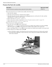
Remove the battery (see "Battery" on page 4-8). 6. Remove the memory module compartment cover (see "Top cover" on page 4-10). Disconnect the fan cable 1 from the computer. 4. Remove the processor fan/heat sink assembly 4. ✎ Due to the adhesive ...the computer by first unplugging the power cord from the AC outlet, and then unplugging the AC adapter from the system board. 2. Remove the top cover (see "Expansion memory module" on page 4-7). 5. Removal and replacement procedures Processor fan/heat sink assembly Description Processor fan/heat sink assembly (includes replacement...
Remove the battery (see "Battery" on page 4-8). 6. Remove the memory module compartment cover (see "Top cover" on page 4-10). Disconnect the fan cable 1 from the computer. 4. Remove the processor fan/heat sink assembly 4. ✎ Due to the adhesive ...the computer by first unplugging the power cord from the AC outlet, and then unplugging the AC adapter from the system board. 2. Remove the top cover (see "Expansion memory module" on page 4-7). 5. Removal and replacement procedures Processor fan/heat sink assembly Description Processor fan/heat sink assembly (includes replacement...
HP ENVY 15 - Maintenance and Service Guide
Page 62
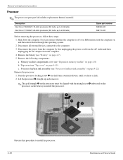
Memory module compartment cover (see "Processor fan/heat sink assembly" on page 4-8) b. Processor fan/heat sink assembly (see "Expansion memory module" on page ...06-GHz) Intel Core i7-720QM 1.60-GHz processor (SC turbo up and remove it down the computer. Remove the following components: a. Top cover (see "Battery" on page 4-10) c. If you hear a click. 2. Disconnect all external devices connected to 2.80-GHz) Spare part ... the processor 2 straight up to the computer. 3. Shut down through the operating system. 2. Remove the battery (see "Top cover" on page 4-7). 5.
Memory module compartment cover (see "Processor fan/heat sink assembly" on page 4-8) b. Processor fan/heat sink assembly (see "Expansion memory module" on page ...06-GHz) Intel Core i7-720QM 1.60-GHz processor (SC turbo up and remove it down the computer. Remove the following components: a. Top cover (see "Battery" on page 4-10) c. If you hear a click. 2. Disconnect all external devices connected to 2.80-GHz) Spare part ... the processor 2 straight up to the computer. 3. Shut down through the operating system. 2. Remove the battery (see "Top cover" on page 4-7). 5.
HP ENVY 15 - Maintenance and Service Guide
Page 63
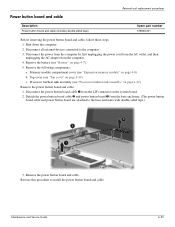
...page 4-22) Remove the power button board and cable: 1. Maintenance and Service Guide 4-25 Reverse this procedure to the computer. 3. Top cover (see "Expansion memory module" on page 4-8) b. Remove the power button board and cable. Disconnect the power from the computer by first...enclosure. (The power button board cable and power button board are attached to the base enclosure with double-sided tape.) 3. Memory module compartment cover (see "Top cover" on page 4-7). 5. Processor fan/heat sink assembly (see "Battery" on page 4-10) c. Remove the battery (see "Processor fan...
...page 4-22) Remove the power button board and cable: 1. Maintenance and Service Guide 4-25 Reverse this procedure to the computer. 3. Top cover (see "Expansion memory module" on page 4-8) b. Remove the power button board and cable. Disconnect the power from the computer by first...enclosure. (The power button board cable and power button board are attached to the base enclosure with double-sided tape.) 3. Memory module compartment cover (see "Top cover" on page 4-7). 5. Processor fan/heat sink assembly (see "Battery" on page 4-10) c. Remove the battery (see "Processor fan...
HP ENVY 15 - Maintenance and Service Guide
Page 64
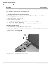
..., follow these steps: 1. Remove the battery (see "Expansion memory module" on page 4-7). 5. Memory module compartment cover (see "Battery" on page 4-8) b. Processor fan/heat sink assembly (see "Top cover" on page 4-22) Remove the power connector cable: 1. Top cover (see "Processor fan/heat sink assembly" on page 4-10) c. Remove the power connector bracket 3. 4. Remove...
..., follow these steps: 1. Remove the battery (see "Expansion memory module" on page 4-7). 5. Memory module compartment cover (see "Battery" on page 4-8) b. Processor fan/heat sink assembly (see "Top cover" on page 4-22) Remove the power connector cable: 1. Top cover (see "Processor fan/heat sink assembly" on page 4-10) c. Remove the power connector bracket 3. 4. Remove...

