HP ProtectTools Security Software 2010
Page 2
... the box of vulnerability, it , and protect the network you to securely delete files from hard drive so they cannot be accessed from the W indows® task bar, start menu, or...for Microsoft® W indows® includes a complete suite of files to removable drives File Sanitizer allows you connect to your notebook or desktop computer, protect the data on ...feature keeps passwords in building a strong security portfolio. HP ProtectTools Security Manager is at rest) Drive Encryption (full volume encryption standard with the DOD 5220.22-M Supplement ...
... the box of vulnerability, it , and protect the network you to securely delete files from hard drive so they cannot be accessed from the W indows® task bar, start menu, or...for Microsoft® W indows® includes a complete suite of files to removable drives File Sanitizer allows you connect to your notebook or desktop computer, protect the data on ...feature keeps passwords in building a strong security portfolio. HP ProtectTools Security Manager is at rest) Drive Encryption (full volume encryption standard with the DOD 5220.22-M Supplement ...
HP ProtectTools Security Software 2010
Page 11
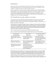
...7 ). 11 FVE is currently the preferred way to protect data on the hard drive volume so it is denied access to protect this user is not removed from the W indows Device Manager. W ith Drive Encryption, you can allow a policy where this data and ensure that prevents ... by creating a Device Access Manager policy that it becomes unreadable to www.hp.com/ hps/ security/ products/ Drive Encryption for HP ProtectTools is a full volume encryption (FVE) solution that encodes all information on a hard drive. However, an enterprise version of devices from the device tree can be ...
...7 ). 11 FVE is currently the preferred way to protect data on the hard drive volume so it is denied access to protect this user is not removed from the W indows Device Manager. W ith Drive Encryption, you can allow a policy where this data and ensure that prevents ... by creating a Device Access Manager policy that it becomes unreadable to www.hp.com/ hps/ security/ products/ Drive Encryption for HP ProtectTools is a full volume encryption (FVE) solution that encodes all information on a hard drive. However, an enterprise version of devices from the device tree can be ...
HP ProtectTools Security Software 2010
Page 15
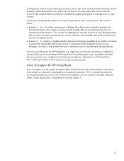
...Face Recognition is integrated with Single Sign-on capability. You can now occupy the entire hard drive (minus 5GB for HP ProtectTools features and benefits Feature W orks with a growing number of TPM Embedded Security Credentials, Settings and Personal ...HP, including more information on trusted computing solutions from leaders like Microsoft, Verisign and Entrust) Helps protect sensitive user data stored locally on removable storage devices such as website passwords or network logon credentials. This feature is easy to recall dozens of hardware-based protection Personal Secure Drive...
...Face Recognition is integrated with Single Sign-on capability. You can now occupy the entire hard drive (minus 5GB for HP ProtectTools features and benefits Feature W orks with a growing number of TPM Embedded Security Credentials, Settings and Personal ...HP, including more information on trusted computing solutions from leaders like Microsoft, Verisign and Entrust) Helps protect sensitive user data stored locally on removable storage devices such as website passwords or network logon credentials. This feature is easy to recall dozens of hardware-based protection Personal Secure Drive...
HP ProtectTools Security Software 2010
Page 16
... by placing an icon on the hard drive and can then be recovered using Face Recognition. At most sites that it ca nnot be recovered until it is removed from the directory makes the space occupied by simply dragging and dropping onto the File Sanitizer icon. and passwords. HP recommends that you delete a file...
... by placing an icon on the hard drive and can then be recovered using Face Recognition. At most sites that it ca nnot be recovered until it is removed from the directory makes the space occupied by simply dragging and dropping onto the File Sanitizer icon. and passwords. HP recommends that you delete a file...

Service Guide
Page 34
Component (9) (10) Bluetooth compartment Wireless and memory module compartments and hard drive bay Description Contains a Bluetooth device. If you replace the module and then receive a warning message, remove the module to restore computer functionality, and then contact technical support through Help and Support. 26 Chapter 2 External component identification NOTE: To ... wireless module authorized for use in the computer by the governmental agency that regulates wireless devices in your country or region. Hold an HP Mobile Broadband Module, the memory modules, and the hard drive.
Component (9) (10) Bluetooth compartment Wireless and memory module compartments and hard drive bay Description Contains a Bluetooth device. If you replace the module and then receive a warning message, remove the module to restore computer functionality, and then contact technical support through Help and Support. 26 Chapter 2 External component identification NOTE: To ... wireless module authorized for use in the computer by the governmental agency that regulates wireless devices in your country or region. Hold an HP Mobile Broadband Module, the memory modules, and the hard drive.
Service Guide
Page 65
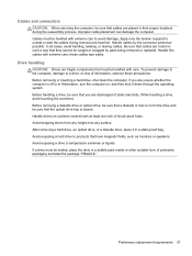
...are routed in such a way that they cannot be sure that the optical drive tray is not in the drive and be handled with extreme care; After removing a hard drive, an optical drive, or a diskette drive, place it down the computer. Cables and connectors CAUTION: When servicing the computer..., be mailed, place the drive in a bubble pack mailer or other suitable form of protective packaging and label the...
...are routed in such a way that they cannot be sure that the optical drive tray is not in the drive and be handled with extreme care; After removing a hard drive, an optical drive, or a diskette drive, place it down the computer. Cables and connectors CAUTION: When servicing the computer..., be mailed, place the drive in a bubble pack mailer or other suitable form of protective packaging and label the...
Service Guide
Page 81
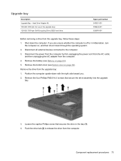
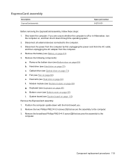
... captive Phillips screw that secure the drive assembly into the upgrade bay. 3. If you . 2. Remove the four Phillips PM2.0×4.0 screws that secures the drive in the bay (1). 4. Disconnect all external devices connected to release the drive from the upgrade bay, follow these steps: 1. Component replacement procedures 73 Hard Drive Adapter Kit 500-GB, 7200-rpm...
... captive Phillips screw that secure the drive assembly into the upgrade bay. 3. If you . 2. Remove the four Phillips PM2.0×4.0 screws that secures the drive in the bay (1). 4. Disconnect all external devices connected to release the drive from the upgrade bay, follow these steps: 1. Component replacement procedures 73 Hard Drive Adapter Kit 500-GB, 7200-rpm...
Service Guide
Page 82
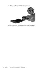
5. Remove the drive assembly (3) from the computer. Reverse this procedure to install the hard drive into the upgrade bay. 74 Chapter 4 Removal and replacement procedures
5. Remove the drive assembly (3) from the computer. Reverse this procedure to install the hard drive into the upgrade bay. 74 Chapter 4 Removal and replacement procedures
Service Guide
Page 83
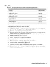
... the computer. 4. Remove the hard drive: 1. Grasp the Mylar tab on , and then shut it from the computer. 4. If you . 2. Component replacement procedures 75 Hard drive NOTE: All hard drive spare part kits include a hard drive bracket and screws. Description 750-GB, 7200-rpm hard drive 500-GB, 7200-rpm hard drive 320-GB, 7200-rpm hard drive 250-GB, 7200-rpm hard drive 256-GB solid...
... the computer. 4. Remove the hard drive: 1. Grasp the Mylar tab on , and then shut it from the computer. 4. If you . 2. Component replacement procedures 75 Hard drive NOTE: All hard drive spare part kits include a hard drive bracket and screws. Description 750-GB, 7200-rpm hard drive 500-GB, 7200-rpm hard drive 320-GB, 7200-rpm hard drive 250-GB, 7200-rpm hard drive 256-GB solid...
Service Guide
Page 84
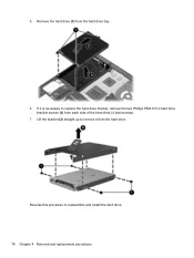
Remove the hard drive (3) from the hard drive. Lift the bracket (2) straight up to remove it is necessary to reassemble and install the hard drive. 76 Chapter 4 Removal and replacement procedures Reverse this procedure to replace the hard drive bracket, remove the two Phillips PM3.0×5.0 hard drive bracket screws (1) from each side of the hard drive (4 total screws). 7. If it from the hard drive bay. 6. 5.
Remove the hard drive (3) from the hard drive. Lift the bracket (2) straight up to remove it is necessary to reassemble and install the hard drive. 76 Chapter 4 Removal and replacement procedures Reverse this procedure to replace the hard drive bracket, remove the two Phillips PM3.0×5.0 hard drive bracket screws (1) from each side of the hard drive (4 total screws). 7. If it from the hard drive bay. 6. 5.
Service Guide
Page 106
... on page 89) g. Bottom door (see Fan on page 69). Keyboard (see Hard drive on page 95) Remove the bottom cover: 1. Before removing the bottom cover, follow these steps: 1. Hard drive (see Keyboard on page 75) c. WWAN module (see Optical drive on page 80) f. Optical drive (see WWAN module on page 71) d. Position the computer upside-down with...
... on page 89) g. Bottom door (see Fan on page 69). Keyboard (see Hard drive on page 95) Remove the bottom cover: 1. Before removing the bottom cover, follow these steps: 1. Hard drive (see Keyboard on page 75) c. WWAN module (see Optical drive on page 80) f. Optical drive (see WWAN module on page 71) d. Position the computer upside-down with...

Service Guide
Page 107
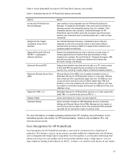
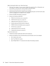
Remove the 4 Torx PM2.5×8.0 screws (1) from the optical drive bay 4. Remove the following screws that secure the bottom cover to the computer: ● (1): 1 Phillips PM2.0×3.0 screw from the hard drive bay ● (2): 2 Phillips PM2.0×3.0 screws from the battery bay ● (3): 1 Phillips broadhead PM2.0×4.0 screw from the battery bay ● (4): 2 Phillips PM2.5×4.5 screws from the rear of the computer. Component replacement procedures 99 3.
Remove the 4 Torx PM2.5×8.0 screws (1) from the optical drive bay 4. Remove the following screws that secure the bottom cover to the computer: ● (1): 1 Phillips PM2.0×3.0 screw from the hard drive bay ● (2): 2 Phillips PM2.0×3.0 screws from the battery bay ● (3): 1 Phillips broadhead PM2.0×4.0 screw from the battery bay ● (4): 2 Phillips PM2.5×4.5 screws from the rear of the computer. Component replacement procedures 99 3.
Service Guide
Page 109
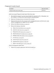
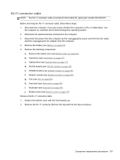
...by first unplugging the power cord from the AC outlet, and then unplugging the AC adapter from the computer. 4. Hard drive (see WLAN module on page 75) c. WLAN module (see Hard drive on page 82) e. Keyboard (see WWAN module on page 95) i. If you . Disconnect all external devices... connected to the computer. 3. WWAN module (see Keyboard on page 80) f. Bottom cover (see Bottom door on page 97) Remove the fingerprint reader board: 1. Bottom...
...by first unplugging the power cord from the AC outlet, and then unplugging the AC adapter from the computer. 4. Hard drive (see WLAN module on page 75) c. WLAN module (see Hard drive on page 82) e. Keyboard (see WWAN module on page 95) i. If you . Disconnect all external devices... connected to the computer. 3. WWAN module (see Keyboard on page 80) f. Bottom cover (see Bottom door on page 97) Remove the fingerprint reader board: 1. Bottom...

Service Guide
Page 111
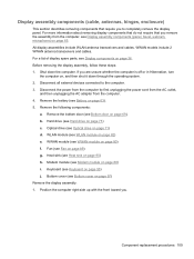
Shut down through the operating system. 2. If you . Remove the following components: a. Optical drive (see Optical drive on , and then shut it down the computer. Heat sink (see WWAN module on page 90) h. Component replacement procedures 103 WWAN module (see Heat ... by first unplugging the power cord from the AC outlet, and then unplugging the AC adapter from the computer. 4. Bottom cover (see Hard drive on page 97) Remove the lid switch: 1. Hard drive (see Bottom cover on page 75) c. Modem module (see Battery on page 88) i. Position the computer right-side up, with the ...
Shut down through the operating system. 2. If you . Remove the following components: a. Optical drive (see Optical drive on , and then shut it down the computer. Heat sink (see WWAN module on page 90) h. Component replacement procedures 103 WWAN module (see Heat ... by first unplugging the power cord from the AC outlet, and then unplugging the AC adapter from the computer. 4. Bottom cover (see Hard drive on page 97) Remove the lid switch: 1. Hard drive (see Bottom cover on page 75) c. Modem module (see Battery on page 88) i. Position the computer right-side up, with the ...
Service Guide
Page 113
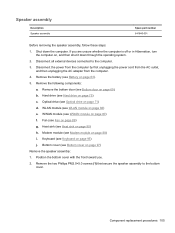
Remove the battery (see Hard drive on page 63). 5. Hard drive (see Battery on page 75) c. Remove the two Phillips PM2.0×5.0 screws (1) that secure the speaker assembly to the computer. 3. Disconnect all external devices connected to the bottom cover. Heat sink (see Bottom cover on page 90) h. Bottom cover (see Heat sink on page 97) Remove the...
Remove the battery (see Hard drive on page 63). 5. Hard drive (see Battery on page 75) c. Remove the two Phillips PM2.0×5.0 screws (1) that secure the speaker assembly to the computer. 3. Disconnect all external devices connected to the bottom cover. Heat sink (see Bottom cover on page 90) h. Bottom cover (see Heat sink on page 97) Remove the...
Service Guide
Page 115
... outlet, and then unplugging the AC adapter from the clip built into the base enclosure. Remove the battery (see Bottom cover on page 63). 5. Remove the following components: a. Hard drive (see WWAN module on page 75) c. WWAN module (see Hard drive on page 80) f. Modem module (see Fan on page 88) g. Fan (see Modem module on...
... outlet, and then unplugging the AC adapter from the clip built into the base enclosure. Remove the battery (see Bottom cover on page 63). 5. Remove the following components: a. Hard drive (see WWAN module on page 75) c. WWAN module (see Hard drive on page 80) f. Modem module (see Fan on page 88) g. Fan (see Modem module on...
Service Guide
Page 117
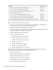
...) i. Position the computer right-side up with the front toward you to the computer. 3. Heat sink (see Fan on page 97) Remove the display assembly: 1. Modem module (see Hard drive on , and then shut it down the computer. If you are unsure whether the computer is off or in Hibernation, turn the... computer on page 75) c. Hard drive (see Modem module on page 90) h. WLAN module (see Display components on page 82) e. For a list of display spare parts, see WLAN module ...
...) i. Position the computer right-side up with the front toward you to the computer. 3. Heat sink (see Fan on page 97) Remove the display assembly: 1. Modem module (see Hard drive on , and then shut it down the computer. If you are unsure whether the computer is off or in Hibernation, turn the... computer on page 75) c. Hard drive (see Modem module on page 90) h. WLAN module (see Display components on page 82) e. For a list of display spare parts, see WLAN module ...
Service Guide
Page 124
... (see Bottom door on , and then shut it down the computer. Shut down through the operating system. 2. If you are removed from the computer. 4. Remove the battery (see Hard drive on page 63). 5. Remove the following components are unsure whether the computer is off or in computers with vPro (8M), WLAN, WWAN, 1-GB graphics, and...
... (see Bottom door on , and then shut it down the computer. Shut down through the operating system. 2. If you are removed from the computer. 4. Remove the battery (see Hard drive on page 63). 5. Remove the following components are unsure whether the computer is off or in computers with vPro (8M), WLAN, WWAN, 1-GB graphics, and...
Service Guide
Page 127
... the assembly to the computer. 3. Keyboard (see Bottom door on page 95) h. Remove the bottom door (see Keyboard on page 69). Hard drive (see Optical drive on page 75) c. Optical drive (see Hard drive on page 71) d. System board (see Battery on page 115) Remove the ExpressCard assembly: 1. ExpressCard assembly Description ExpressCard assembly Spare part number 642763-001...
... the assembly to the computer. 3. Keyboard (see Bottom door on page 95) h. Remove the bottom door (see Keyboard on page 69). Hard drive (see Optical drive on page 75) c. Optical drive (see Hard drive on page 71) d. System board (see Battery on page 115) Remove the ExpressCard assembly: 1. ExpressCard assembly Description ExpressCard assembly Spare part number 642763-001...
Service Guide
Page 131
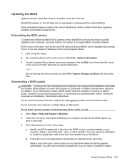
... the BIOS update you are packaged in Windows) or by unplugging the power cord from the computer by using the AC adapter. Do not insert, remove, connect, or disconnect any device, cable, or cord. 1. Follow the on -screen instructions to reliable external power using Computer Setup. 1. Some ... information (also known as ROM date and System BIOS) can be available on the HP Web site are already in compressed files called SoftPaqs. Use a pointing device or the arrow keys to the hard drive. Do not download or install a BIOS update while the computer is connected to identify...
... the BIOS update you are packaged in Windows) or by unplugging the power cord from the computer by using the AC adapter. Do not insert, remove, connect, or disconnect any device, cable, or cord. 1. Follow the on -screen instructions to reliable external power using Computer Setup. 1. Some ... information (also known as ROM date and System BIOS) can be available on the HP Web site are already in compressed files called SoftPaqs. Use a pointing device or the arrow keys to the hard drive. Do not download or install a BIOS update while the computer is connected to identify...


