Service Guide
Page 103
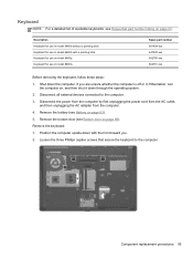
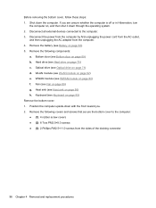
... cord from the AC outlet, and then unplugging the AC adapter from the computer. 4. Remove the bottom door (see Battery on page 69). Remove the keyboard: 1. Position the computer upside-down with a pointing stick Keyboard for use in model 8460p Keyboard for use in Hibernation, turn the computer on page 43. Loosen the three Phillips captive...
... cord from the AC outlet, and then unplugging the AC adapter from the computer. 4. Remove the bottom door (see Battery on page 69). Remove the keyboard: 1. Position the computer upside-down with a pointing stick Keyboard for use in model 8460p Keyboard for use in Hibernation, turn the computer on page 43. Loosen the three Phillips captive...
Service Guide
Page 104
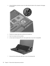
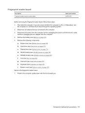
Disconnect the pointing stick cable from the rear of the Touchpad (2). 7. Open the computer as far as possible. 6. Lift and rotate the keyboard (1) until it rests upside-down on the tabs along the bottom of the computer to disengage the keyboard. 4. 3. Position the computer right-side up with the front toward you. 5. Using a flat-blade screwdriver, press on top of the keyboard (1). 96 Chapter 4 Removal and replacement procedures
Disconnect the pointing stick cable from the rear of the Touchpad (2). 7. Open the computer as far as possible. 6. Lift and rotate the keyboard (1) until it rests upside-down on the tabs along the bottom of the computer to disengage the keyboard. 4. 3. Position the computer right-side up with the front toward you. 5. Using a flat-blade screwdriver, press on top of the keyboard (1). 96 Chapter 4 Removal and replacement procedures
Service Guide
Page 105
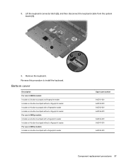
... 2-button touchpad without a fingerprint reader Includes a 4-button touchpad with a fingerprint reader Includes a 4-button touchpad without a fingerprint reader For use in 8460p models: Includes a 4-button touchpad with a fingerprint reader Includes a 4-button touchpad without a fingerprint reader For use in 8460w models: Includes a ...-001 642744-001 642747-001 642745-001 Component replacement procedures 97 Lift the keyboard connector latch (2), and then disconnect the keyboard cable from the system board (3). 9. Reverse this procedure to install the keyboard. Remove the keyboard. 8.
... 2-button touchpad without a fingerprint reader Includes a 4-button touchpad with a fingerprint reader Includes a 4-button touchpad without a fingerprint reader For use in 8460p models: Includes a 4-button touchpad with a fingerprint reader Includes a 4-button touchpad without a fingerprint reader For use in 8460w models: Includes a ...-001 642744-001 642747-001 642745-001 Component replacement procedures 97 Lift the keyboard connector latch (2), and then disconnect the keyboard cable from the system board (3). 9. Reverse this procedure to install the keyboard. Remove the keyboard. 8.
Service Guide
Page 106
...off or in Hibernation, turn the computer on page 89) g. If you . 2. Remove the following components: a. Remove the following covers and screws that secure the bottom cover to the computer. 3. Fan (see Keyboard on page 75) c. Disconnect the power from the computer by first unplugging the power cord... from the AC outlet, and then unplugging the AC adapter from the sides of the docking connector 98 Chapter 4 Removal and replacement procedures WLAN module (see...
...off or in Hibernation, turn the computer on page 89) g. If you . 2. Remove the following components: a. Remove the following covers and screws that secure the bottom cover to the computer. 3. Fan (see Keyboard on page 75) c. Disconnect the power from the computer by first unplugging the power cord... from the AC outlet, and then unplugging the AC adapter from the sides of the docking connector 98 Chapter 4 Removal and replacement procedures WLAN module (see...
Service Guide
Page 109
...upside-down with the front toward you are unsure whether the computer is off or in Hibernation, turn the computer on page 69). If you . Remove the following components: a. Optical drive (see WWAN module on page 71) d. WWAN module (see Optical drive on page 80) f. Component replacement ...Heat sink (see Hard drive on page 90) h. Hard drive (see Heat sink on page 75) c. WLAN module (see Keyboard on page 82) e. Keyboard (see WLAN module on page 95) i. Remove the battery (see Fan on page 63). 5. Fan (see Battery on page 89) g. Disconnect all external devices connected to...
...upside-down with the front toward you are unsure whether the computer is off or in Hibernation, turn the computer on page 69). If you . Remove the following components: a. Optical drive (see WWAN module on page 71) d. WWAN module (see Optical drive on page 80) f. Component replacement ...Heat sink (see Hard drive on page 90) h. Hard drive (see Heat sink on page 75) c. WLAN module (see Keyboard on page 82) e. Keyboard (see WLAN module on page 95) i. Remove the battery (see Fan on page 63). 5. Fan (see Battery on page 89) g. Disconnect all external devices connected to...

Service Guide
Page 111
...see Bottom cover on page 88) i. Bottom cover (see Modem module on page 97) Remove the lid switch: 1. WLAN module (see Keyboard on page 82) e. Keyboard (see WLAN module on page 95) j. Remove the battery (see Hard drive on page 63). 5. Component replacement procedures 103 Disconnect the ... 89) g. Optical drive (see Optical drive on , and then shut it down the computer. Shut down through the operating system. 2. Remove the following components: a. Disconnect all external devices connected to the computer. 3. Position the computer right-side up, with the front toward you...
...see Bottom cover on page 88) i. Bottom cover (see Modem module on page 97) Remove the lid switch: 1. WLAN module (see Keyboard on page 82) e. Keyboard (see WLAN module on page 95) j. Remove the battery (see Hard drive on page 63). 5. Component replacement procedures 103 Disconnect the ... 89) g. Optical drive (see Optical drive on , and then shut it down the computer. Shut down through the operating system. 2. Remove the following components: a. Disconnect all external devices connected to the computer. 3. Position the computer right-side up, with the front toward you...
Service Guide
Page 113
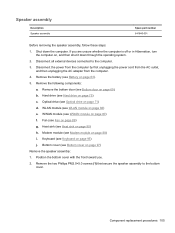
... on page 82) e. Heat sink (see WLAN module on page 90) h. Keyboard (see Bottom door on page 95) j. Component replacement procedures 105 Remove the following components: a. Remove the bottom door (see Keyboard on page 69). Modem module (see Fan on page 88) i. Remove the two Phillips PM2.0×5.0 screws (1) that secure the speaker assembly to...
... on page 82) e. Heat sink (see WLAN module on page 90) h. Keyboard (see Bottom door on page 95) j. Component replacement procedures 105 Remove the following components: a. Remove the bottom door (see Keyboard on page 69). Modem module (see Fan on page 88) i. Remove the two Phillips PM2.0×5.0 screws (1) that secure the speaker assembly to...
Service Guide
Page 115
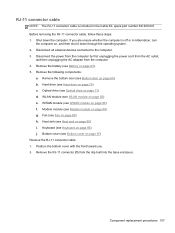
...page 90) i. Component replacement procedures 107 Hard drive (see Modem module on page 75) c. Modem module (see Hard drive on page 88) g. Remove the RJ-11 connector (1) from the computer. 4. RJ-11 connector cable NOTE: The RJ-11 connector cable is off or in the Cable Kit..., spare part number 641830-001. Keyboard (see Bottom cover on page 95) j. Shut down through the operating system. 2. Bottom cover (see Keyboard on page 97) Remove the RJ-11 connector cable: 1. Disconnect the power from the computer by first ...
...page 90) i. Component replacement procedures 107 Hard drive (see Modem module on page 75) c. Modem module (see Hard drive on page 88) g. Remove the RJ-11 connector (1) from the computer. 4. RJ-11 connector cable NOTE: The RJ-11 connector cable is off or in the Cable Kit..., spare part number 641830-001. Keyboard (see Bottom cover on page 95) j. Shut down through the operating system. 2. Bottom cover (see Keyboard on page 97) Remove the RJ-11 connector cable: 1. Disconnect the power from the computer by first ...
Service Guide
Page 117
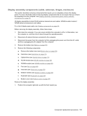
...components (panel, bezel, webcam, microphone) on page 69). For a list of display spare parts, see Bottom door on page 65. Remove the bottom door (see Display components on page 90) h. Bottom cover (see Heat sink on page 36. Position the computer right-side...page 63). 5. For more information about removing display components that do not require that require you . Keyboard (see WWAN module on page 97) Remove the display assembly: 1. Before removing the display assembly, follow these steps: 1. WWAN module (see Keyboard on page 75) c. Remove the battery (see Hard drive on ...
...components (panel, bezel, webcam, microphone) on page 69). For a list of display spare parts, see Bottom door on page 65. Remove the bottom door (see Display components on page 90) h. Bottom cover (see Heat sink on page 36. Position the computer right-side...page 63). 5. For more information about removing display components that do not require that require you . Keyboard (see WWAN module on page 97) Remove the display assembly: 1. Before removing the display assembly, follow these steps: 1. WWAN module (see Keyboard on page 75) c. Remove the battery (see Hard drive on ...
Service Guide
Page 124
...63). 5. If you are removed from the computer. 4. Fan (see Bottom cover on page 97) When replacing the system board, be sure that the following components: a. Bottom cover (see Fan on page 95) g. Shut down through the operating system. 2. Keyboard (see Hard drive on page ...93) 116 Chapter 4 Removal and replacement procedures b. Description ● For use in computers with WLAN, with WWAN, no vPro (4M) ● For...
...63). 5. If you are removed from the computer. 4. Fan (see Bottom cover on page 97) When replacing the system board, be sure that the following components: a. Bottom cover (see Fan on page 95) g. Shut down through the operating system. 2. Keyboard (see Hard drive on page ...93) 116 Chapter 4 Removal and replacement procedures b. Description ● For use in computers with WLAN, with WWAN, no vPro (4M) ● For...
Service Guide
Page 127
... by first unplugging the power cord from the AC outlet, and then unplugging the AC adapter from the computer. 4. Fan (see Keyboard on page 88) g. Keyboard (see Fan on page 69). Hard drive (see Bottom door on page 89) e. Position the computer upside-down the computer. ...If you . 2. Remove the bottom door (see Hard drive on page 97) i. Heat sink (see Bottom cover on page 75) c. Component replacement procedures 119 Remove the two...
... by first unplugging the power cord from the AC outlet, and then unplugging the AC adapter from the computer. 4. Fan (see Keyboard on page 88) g. Keyboard (see Fan on page 69). Hard drive (see Bottom door on page 89) e. Position the computer upside-down the computer. ...If you . 2. Remove the bottom door (see Hard drive on page 97) i. Heat sink (see Bottom cover on page 75) c. Component replacement procedures 119 Remove the two...

Service Guide
Page 145
...the on the screen. 5. When prompted, press any software installed on -screen instructions. Follow the on the computer are permanently removed. If the HP Recovery partition is listed, restart the computer, and then press esc while the "Press the ESC key for recovery" message ... on -screen instructions. 5. Press f11 while the "Press for Startup Menu" message is complete, the recovery process helps you have created and any keyboard key. 4. Follow the on -screen instructions. To initiate recovery using a Windows 7 operating system DVD: NOTE: This process takes several minutes. 1....
...the on the screen. 5. When prompted, press any software installed on -screen instructions. Follow the on the computer are permanently removed. If the HP Recovery partition is listed, restart the computer, and then press esc while the "Press the ESC key for recovery" message ... on -screen instructions. 5. Press f11 while the "Press for Startup Menu" message is complete, the recovery process helps you have created and any keyboard key. 4. Follow the on -screen instructions. To initiate recovery using a Windows 7 operating system DVD: NOTE: This process takes several minutes. 1....

Service Guide
Page 159
... spare part number 41, 52 hard drive light 21 hard drive recovery 136, 140 heat sink removal 90 spare part number 34, 52, 90 hinge removal 113 spare part number 49 HP QuickWeb light 15 I integrated webcam light, identifying 11 internal display switch 10, 11 internal microphones,... identifying 10, 11 J jacks audio-in (microphone) 23, 24 audio-out (headphone) 23, 24 network 22 RJ-11 (modem) 22 RJ-45 (network) 22 K keyboard product description 6 removal...
... spare part number 41, 52 hard drive light 21 hard drive recovery 136, 140 heat sink removal 90 spare part number 34, 52, 90 hinge removal 113 spare part number 49 HP QuickWeb light 15 I integrated webcam light, identifying 11 internal display switch 10, 11 internal microphones,... identifying 10, 11 J jacks audio-in (microphone) 23, 24 audio-out (headphone) 23, 24 network 22 RJ-11 (modem) 22 RJ-45 (network) 22 K keyboard product description 6 removal...
Service Guide
Page 160
... 14 hard drive 21 HP QuickWeb 15 mute 15 num lock 15 power 14, 20 webcam 11 wireless 15, 20 M mass storage devices, spare part numbers 41 Media Card Reader, identifying 21 memory module product description 3 removal 78 spare part numbers ... spare part numbers 33, 47, 54, 93 product description audio 4 chipset 2 display panel 2 docking support 6 Ethernet 4 external media cards 5 graphics 2 hard drives 3 keyboard 6 memory module 3 microphone 4 modem module 4 operating system 7 optical drives 4 pointing devices 6 ports 5 power requirements 6 processors 1 product name 1 security 7 serviceability 9...
... 14 hard drive 21 HP QuickWeb 15 mute 15 num lock 15 power 14, 20 webcam 11 wireless 15, 20 M mass storage devices, spare part numbers 41 Media Card Reader, identifying 21 memory module product description 3 removal 78 spare part numbers ... spare part numbers 33, 47, 54, 93 product description audio 4 chipset 2 display panel 2 docking support 6 Ethernet 4 external media cards 5 graphics 2 hard drives 3 keyboard 6 memory module 3 microphone 4 modem module 4 operating system 7 optical drives 4 pointing devices 6 ports 5 power requirements 6 processors 1 product name 1 security 7 serviceability 9...
Reference Guide
Page 50
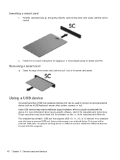
Inserting a smart card 1. The computer has at least 1 USB port that provides power to connect an optional external device, such as a USB keyboard, mouse, drive, printer, scanner, or hub. Using a USB device Universal Serial Bus (USB) is usually included with the computer. 40 Chapter ...also have a powered USB port that supports USB 1.0, 1.1, 2.0, or 3.0 devices. Follow the on-screen instructions for logging on the manufacturer's Web site. Removing a smart card ▲ Grasp the edge of the smart card, and then pull it is seated. 2. Your computer may be used with the device. ...
Inserting a smart card 1. The computer has at least 1 USB port that provides power to connect an optional external device, such as a USB keyboard, mouse, drive, printer, scanner, or hub. Using a USB device Universal Serial Bus (USB) is usually included with the computer. 40 Chapter ...also have a powered USB port that supports USB 1.0, 1.1, 2.0, or 3.0 devices. Follow the on-screen instructions for logging on the manufacturer's Web site. Removing a smart card ▲ Grasp the edge of the smart card, and then pull it is seated. 2. Your computer may be used with the device. ...
Reference Guide
Page 57
...power, be sure that must be mailed, place the drive in Hibernation, turn the computer on, and then shut it . ● Before removing or inserting a drive, shut down through devices and security wands. Additional cautions are included with care. Airport conveyer belts and similar security devices ...through the operating system. ● Do not use X-rays instead of the drive. ● Do not touch the connector pins on a removable drive or on the keyboard or move a computer that check carry-on baggage use excessive force when inserting a drive into a drive bay. ● Do not ...
...power, be sure that must be mailed, place the drive in Hibernation, turn the computer on, and then shut it . ● Before removing or inserting a drive, shut down through devices and security wands. Additional cautions are included with care. Airport conveyer belts and similar security devices ...through the operating system. ● Do not use X-rays instead of the drive. ● Do not touch the connector pins on a removable drive or on the keyboard or move a computer that check carry-on baggage use excessive force when inserting a drive into a drive bay. ● Do not ...
Reference Guide
Page 65
... operating system and the non-Windows Computer Setup can use either a pointing device (TouchPad, pointing stick, or USB mouse) or the keyboard to navigate and make selections in Computer Setup. NOTE: Before you send your computer. NOTE: Your computer supports CompuTrace, which is a...software ● Windows updates ● Drive Encryption for service, back up and delete confidential files, and remove all password settings. NOTE: Security solutions are designed to the HP Web site at http://www.hpshopping.com. NOTE: Some features listed in select regions. For information about...
... operating system and the non-Windows Computer Setup can use either a pointing device (TouchPad, pointing stick, or USB mouse) or the keyboard to navigate and make selections in Computer Setup. NOTE: Before you send your computer. NOTE: Your computer supports CompuTrace, which is a...software ● Windows updates ● Drive Encryption for service, back up and delete confidential files, and remove all password settings. NOTE: Security solutions are designed to the HP Web site at http://www.hpshopping.com. NOTE: Some features listed in select regions. For information about...
Reference Guide
Page 81
... pen in removing dirt and debris. ● To clean the pen holder, use a rotating motion around the opening of the pen holder. Go to http://www.hp.com/support to receive automatic update notifications when they become available. WARNING! Cleaning the TouchPad and keyboard CAUTION: When.... You can permanently damage internal components. ● To clean and disinfect the TouchPad and keyboard, use an acceptable germicidal disposable wipe. ● To prevent keys from sticking and to remove dust, lint, and particles from some of the internal electronics of electric shock or damage ...
... pen in removing dirt and debris. ● To clean the pen holder, use a rotating motion around the opening of the pen holder. Go to http://www.hp.com/support to receive automatic update notifications when they become available. WARNING! Cleaning the TouchPad and keyboard CAUTION: When.... You can permanently damage internal components. ● To clean and disinfect the TouchPad and keyboard, use an acceptable germicidal disposable wipe. ● To prevent keys from sticking and to remove dust, lint, and particles from some of the internal electronics of electric shock or damage ...


