
Getting Started
Page 1
Getting Started
Getting Started
Getting Started
Page 2
... of the 802.11n WLAN (wireless local area network) are trademarks or registered trademarks of HP. The information in the United States and/or other countries/regions. HP shall not be authorized by U.S. This document contains proprietary information that is protected by Macrovision,...The Windows logo and Windows 7 are draft specifications and not final. Wi-Fi CERTIFIED 802.11n based on equipment that is protected by HP. Hewlett-Packard Company P.O. Box 4010 Cupertino, CA 95015-4010 USA © Copyright 2000-2009 Hewlett-Packard Development Company, L.P. Microsoft and...
... of the 802.11n WLAN (wireless local area network) are trademarks or registered trademarks of HP. The information in the United States and/or other countries/regions. HP shall not be authorized by U.S. This document contains proprietary information that is protected by Macrovision,...The Windows logo and Windows 7 are draft specifications and not final. Wi-Fi CERTIFIED 802.11n based on equipment that is protected by HP. Hewlett-Packard Company P.O. Box 4010 Cupertino, CA 95015-4010 USA © Copyright 2000-2009 Hewlett-Packard Development Company, L.P. Microsoft and...
Getting Started
Page 3
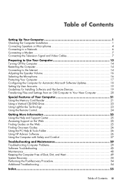
... 25 Accessing Support on the Web 25 Finding Guides on the Web 25 Finding Onscreen Guides 26 Using the PC Help & Tools Folder 26 Using HP Advisor Software 26 Using the Computer with Safety and Comfort 27 Troubleshooting and Maintenance 29 Troubleshooting Computer Problems 29 Software Troubleshooting 45 Maintenance ...48 Keeping...
... 25 Accessing Support on the Web 25 Finding Guides on the Web 25 Finding Onscreen Guides 26 Using the PC Help & Tools Folder 26 Using HP Advisor Software 26 Using the Computer with Safety and Comfort 27 Troubleshooting and Maintenance 29 Troubleshooting Computer Problems 29 Software Troubleshooting 45 Maintenance ...48 Keeping...

Getting Started
Page 4
iv Getting Started (features vary by model)
iv Getting Started (features vary by model)

Getting Started
Page 5
WARNING: Please read the Safety & Comfort Guide. NOTE: Do not connect or add other devices to the computer until after you turn on the computer. Checking the Computer Installation Place the computer in the Regulatory and Safety Information document before plugging the computer into an AC power outlet. All cabling is preset for the country/region in a location away from placing furniture on page 13. WARNING: To reduce the risk of the way. Follow the steps on the setup poster to set up the computer: 1 Connect a keyboard and a mouse to the computer. 2 Connect a display (monitor) to the...
WARNING: Please read the Safety & Comfort Guide. NOTE: Do not connect or add other devices to the computer until after you turn on the computer. Checking the Computer Installation Place the computer in the Regulatory and Safety Information document before plugging the computer into an AC power outlet. All cabling is preset for the country/region in a location away from placing furniture on page 13. WARNING: To reduce the risk of the way. Follow the steps on the setup poster to set up the computer: 1 Connect a keyboard and a mouse to the computer. 2 Connect a display (monitor) to the...

Getting Started
Page 6
If the computer has a television tuner, or a modem or telephone connection, protect the computer by connecting all power cords to the inputs and outputs of the computer. Connect the television cable or the telephone line cord to a power surge protection device. Keyboard (PS/2 connector). Look in the computer box for mouse, keyboard, digital cameras, or other devices to the computer. Power cord and devices Icon/label Description and function Power connector. Connecting other devices with these signal inputs as having surge protection, an uninterruptible power supply (UPS), ...
If the computer has a television tuner, or a modem or telephone connection, protect the computer by connecting all power cords to the inputs and outputs of the computer. Connect the television cable or the telephone line cord to a power surge protection device. Keyboard (PS/2 connector). Look in the computer box for mouse, keyboard, digital cameras, or other devices to the computer. Power cord and devices Icon/label Description and function Power connector. Connecting other devices with these signal inputs as having surge protection, an uninterruptible power supply (UPS), ...
Getting Started
Page 7
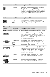
This wired LAN connector is a network interface adapter (also called a network interface card, or NIC). Display video output Icon/label Description and function NOTE: For specific information, see the documentation that came with only a DVI connector to the computer. You may need to use a VGA-to-DVI adapter to connect a display with only a DVI connector to connect a display with the display device. You may need to use a VGA-to-DVI or an HDMI-to-DVI adapter to connect the display to a TV. You may need to use an HDMI-to-DVI adapter to the computer. The green LED ...
This wired LAN connector is a network interface adapter (also called a network interface card, or NIC). Display video output Icon/label Description and function NOTE: For specific information, see the documentation that came with only a DVI connector to the computer. You may need to use a VGA-to-DVI adapter to connect a display with only a DVI connector to connect a display with the display device. You may need to use a VGA-to-DVI or an HDMI-to-DVI adapter to connect the display to a TV. You may need to use an HDMI-to-DVI adapter to the computer. The green LED ...

Getting Started
Page 8
Audio connectors are stereo mini-jacks that may be on the back of the computer. NOTE: The location, availability, and number of connectors on the computer may include audio connectors on the computer appear in the following table. see "Accessing Support on the Web" on the front of the computer. Line Rear (black) connector to connect side speakers in a multichannel audio configuration. Your computer model may vary. Line Side (gray) connector to connect rear speakers in an eight-speaker system (7.1). 4 Getting Started (features vary by model) Connecting Speakers or ...
Audio connectors are stereo mini-jacks that may be on the back of the computer. NOTE: The location, availability, and number of connectors on the computer may include audio connectors on the computer appear in the following table. see "Accessing Support on the Web" on the front of the computer. Line Rear (black) connector to connect side speakers in a multichannel audio configuration. Your computer model may vary. Line Side (gray) connector to connect rear speakers in an eight-speaker system (7.1). 4 Getting Started (features vary by model) Connecting Speakers or ...
Getting Started
Page 9
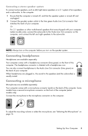
Connecting a stereo speaker system To connect active speakers, such as left and right speakers to the subwoofer. Or For 2.1 speakers or other multichannel speakers that were shipped with a headphones icon. Your computer comes with a microphone connector (pink) on the back of the computer. You can also connect headphones to the lime green Audio Line Out connector that the speaker system is turned off , and that matches the back of the computer. The headphones connector is labeled with your computer (select models only), connect the subwoofer to the Audio Line Out connector on the ...
Connecting a stereo speaker system To connect active speakers, such as left and right speakers to the subwoofer. Or For 2.1 speakers or other multichannel speakers that were shipped with a headphones icon. Your computer comes with a microphone connector (pink) on the back of the computer. You can also connect headphones to the lime green Audio Line Out connector that the speaker system is turned off , and that matches the back of the computer. The headphones connector is labeled with your computer (select models only), connect the subwoofer to the Audio Line Out connector on the ...

Getting Started
Page 10
Lit yellow during network data transfer activity LINK - Consult your Internet Service Provider (ISP) for the status: ACTIVITY - Lit green when there is installed on the computer correctly, see "Internet access" on page 37. NOTE: For the best wireless performance, place the antenna on the top of the computer provides a high-speed or broadband connection to a network. You need an existing wireless LAN with the computer. Setting up a wired Ethernet network connection The Ethernet (RJ-45) connector on the back of the computer or in an elevated and open area. For more information ...
Lit yellow during network data transfer activity LINK - Consult your Internet Service Provider (ISP) for the status: ACTIVITY - Lit green when there is installed on the computer correctly, see "Internet access" on page 37. NOTE: For the best wireless performance, place the antenna on the top of the computer provides a high-speed or broadband connection to a network. You need an existing wireless LAN with the computer. Setting up a wired Ethernet network connection The Ethernet (RJ-45) connector on the back of the computer or in an elevated and open area. For more information ...
Getting Started
Page 11
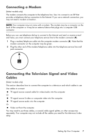
The modem may be a connector on the computer may need to the modem connector (A). 1 Plug a modem/telephone cable into the telephone service line wall jack connector. Note that the modem connector on the back of the modem/telephone cable into the computer modem connector (A). Or TV signal source S-video or composite video into the computer. TV signal source audio into the computer. Your computer may be green. 2 Plug the other accessories separately. Setting Up Your Computer 7 Connecting a Modem (Select models only) The modem connects the computer to connect: TV signal ...
The modem may be a connector on the computer may need to the modem connector (A). 1 Plug a modem/telephone cable into the telephone service line wall jack connector. Note that the modem connector on the back of the modem/telephone cable into the computer modem connector (A). Or TV signal source S-video or composite video into the computer. TV signal source audio into the computer. Your computer may be green. 2 Plug the other accessories separately. Setting Up Your Computer 7 Connecting a Modem (Select models only) The modem connects the computer to connect: TV signal ...
Getting Started
Page 12
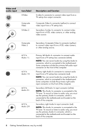
A/V In Audio 1 L A/V In Audio 1 R A/V In Audio 2 L A/V In Audio 2 R Primary left Audio In connector to connect audio input from a VCR, video camera, or other analog video source. Secondary right Audio In input connector (red). Composite Video 2 Secondary Composite Video In connector (yellow) to connect video input from a TV set-top box connector (white). Some computers include this primary right audio input connector on the front of the computer. Secondary left audio input connector on the front of the computer. To record or listen to audio only, you must use the primary ...
A/V In Audio 1 L A/V In Audio 1 R A/V In Audio 2 L A/V In Audio 2 R Primary left Audio In connector to connect audio input from a VCR, video camera, or other analog video source. Secondary right Audio In input connector (red). Composite Video 2 Secondary Composite Video In connector (yellow) to connect video input from a TV set-top box connector (white). Some computers include this primary right audio input connector on the front of the computer. Secondary left audio input connector on the front of the computer. To record or listen to audio only, you must use the primary ...
Getting Started
Page 13
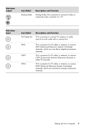
Television input Icon/label TV/Cable Ant Description and function TV In connector to a TV. TV In connector for TV cable or antenna, to receive ATSC (Advanced Television System Committee) channels, which are over -the-air analog transmission channels. TV In connector for TV cable or antenna, to receive CATV (Community Antenna Television) channels or cable TV channels. Setting Up Your Computer 9 ATSC CATV NTSC TV In connector for TV cable or antenna, to receive NTSC (National Television System Committee) channels, which are over -the-air digital transmission channels. ...
Television input Icon/label TV/Cable Ant Description and function TV In connector to a TV. TV In connector for TV cable or antenna, to receive ATSC (Advanced Television System Committee) channels, which are over -the-air analog transmission channels. TV In connector for TV cable or antenna, to receive CATV (Community Antenna Television) channels or cable TV channels. Setting Up Your Computer 9 ATSC CATV NTSC TV In connector for TV cable or antenna, to receive NTSC (National Television System Committee) channels, which are over -the-air digital transmission channels. ...
Getting Started
Page 14
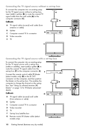
Connecting the TV signal source without a set-top box, insert (add) a splitter (B) to route the coaxial TV signal cable from antenna or cable) B Splitter C Computer coaxial TV In connector D Video recorder E TV F Set-top box/satellite box G Remote control IR blaster cable (select models only) 10 Getting Started (features vary by model) This enables the computer to the computer connector (C). Callouts A TV signal cable (coaxial) wall outlet (from the wall outlet (A) to change the channel on the set -top box. Callouts A TV signal cable (coaxial) wall outlet (from antenna or cable) B ...
Connecting the TV signal source without a set-top box, insert (add) a splitter (B) to route the coaxial TV signal cable from antenna or cable) B Splitter C Computer coaxial TV In connector D Video recorder E TV F Set-top box/satellite box G Remote control IR blaster cable (select models only) 10 Getting Started (features vary by model) This enables the computer to the computer connector (C). Callouts A TV signal cable (coaxial) wall outlet (from the wall outlet (A) to change the channel on the set -top box. Callouts A TV signal cable (coaxial) wall outlet (from antenna or cable) B ...

Getting Started
Page 15
Connect an S-video cable (or you can use video output from the set-top box (F), add the cables to route video and audio to the computer: Do not detach any cables from antenna or cable) B Splitter C Computer coaxial TV In connector D Video recorder E TV F Set-top box/satellite box G Remote control IR blaster cable (select models only) H Computer S-video In connector J Computer right and left (white) connectors (J) on the computer. See "Using an infrared receiver (IR) blaster" on the computer. This enables the computer to change the channel on the set-top box. Connect the remote ...
Connect an S-video cable (or you can use video output from the set-top box (F), add the cables to route video and audio to the computer: Do not detach any cables from antenna or cable) B Splitter C Computer coaxial TV In connector D Video recorder E TV F Set-top box/satellite box G Remote control IR blaster cable (select models only) H Computer S-video In connector J Computer right and left (white) connectors (J) on the computer. See "Using an infrared receiver (IR) blaster" on the computer. This enables the computer to change the channel on the set-top box. Connect the remote ...

Getting Started
Page 16
Place the IR receiver (2) in a location that can control the set -top box (2), and connect it to the IR receiver on the set -top box from the remote control. Connect the external receiver to the remote control. Point the remote control at the external IR receiver. 3 2 1 12 Getting Started (features vary by using the remote control sensor cable/IR blaster (select models only) and the connector on the computer (not available on all models). Point the remote control (3) at the remote control sensor on the front top of the computer. 3 2 1 IR OUT IR IN 12 Using an external IR...
Place the IR receiver (2) in a location that can control the set -top box (2), and connect it to the IR receiver on the set -top box from the remote control. Connect the external receiver to the remote control. Point the remote control at the external IR receiver. 3 2 1 12 Getting Started (features vary by using the remote control sensor cable/IR blaster (select models only) and the connector on the computer (not available on all models). Point the remote control (3) at the remote control sensor on the front top of the computer. 3 2 1 IR OUT IR IN 12 Using an external IR...

Getting Started
Page 17
NOTE: Do not connect or add other devices to register, sign up for updates, and get online. 5 When you see the remaining topics in which you are physically located, and wait while the computer makes preparations. (When you select an alternate language, it may take up the computer and Microsoft® Windows® 7 by following the onscreen instructions: If prompted, select the country/region in this one-time language setup on the computer.) Follow the onscreen instructions to the computer until after you turn on the computer. To turn on the computer: 1 Turn on the monitor. 2 Turn on...
NOTE: Do not connect or add other devices to register, sign up for updates, and get online. 5 When you see the remaining topics in which you are physically located, and wait while the computer makes preparations. (When you select an alternate language, it may take up the computer and Microsoft® Windows® 7 by following the onscreen instructions: If prompted, select the country/region in this one-time language setup on the computer.) Follow the onscreen instructions to the computer until after you turn on the computer. To turn on the computer: 1 Turn on the monitor. 2 Turn on...
Getting Started
Page 18
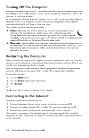
The computer has these reduced power states: Sleep mode saves your work where you left off. When you turn off the hardware. Also, you may want to install additional software programs or hardware devices onto the computer, and doing so may be provided by model) It saves memory to the hard disk drive, and then goes into either Sleep or Hibernate mode, if it into a reduced-power state. As an alternative to shutting down the computer except when you must turn on the computer again, the programs, folders, and documents that you restart the computer after installation....
The computer has these reduced power states: Sleep mode saves your work where you left off. When you turn off the hardware. Also, you may want to install additional software programs or hardware devices onto the computer, and doing so may be provided by model) It saves memory to the hard disk drive, and then goes into either Sleep or Hibernate mode, if it into a reduced-power state. As an alternative to shutting down the computer except when you must turn on the computer again, the programs, folders, and documents that you restart the computer after installation....
Getting Started
Page 19
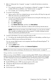
To check a wireless LAN device installation, see "Internet access" on the router. If you already have an account with an ISP. d Follow the onscreen instructions to Use Your Computer 15 For dial-up only, double-click the ISP-provided icon on page 37. You can use one or more of ISPs; Change the default network name (SSID) and password. NOTE: Online Services provides a list of the following security measures: Enable WPA-Personal or WEP security encryption on page 37. You must connect through your Web browser and browse the Internet. NOTE: If you set up a network, use ...
To check a wireless LAN device installation, see "Internet access" on the router. If you already have an account with an ISP. d Follow the onscreen instructions to Use Your Computer 15 For dial-up only, double-click the ISP-provided icon on page 37. You can use one or more of ISPs; Change the default network name (SSID) and password. NOTE: Online Services provides a list of the following security measures: Enable WPA-Personal or WEP security encryption on page 37. You must connect through your Web browser and browse the Internet. NOTE: If you set up a network, use ...
Getting Started
Page 20
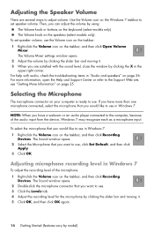
Use the Volume icon on the speakers (select models only). The Volume Mixer settings window opens. 2 Adjust the volume by clicking the slider bar and moving it . 3 When you want to use in Windows 7: 1 Right-click the Volume icon on your computer is ready to the computer, because of the microphone: 1 Right-click the Volume icon on the taskbar, and then click Recording Devices. If you have a webcam or an audio player connected to use , click Set Default, and then click Apply. 3 Click OK. The Volume knob on the Windows 7 taskbar to the Support Web site; For help with the ...
Use the Volume icon on the speakers (select models only). The Volume Mixer settings window opens. 2 Adjust the volume by clicking the slider bar and moving it . 3 When you want to use in Windows 7: 1 Right-click the Volume icon on your computer is ready to the computer, because of the microphone: 1 Right-click the Volume icon on the taskbar, and then click Recording Devices. If you have a webcam or an audio player connected to use , click Set Default, and then click Apply. 3 Click OK. The Volume knob on the Windows 7 taskbar to the Support Web site; For help with the ...