Setup Poster
Page 19
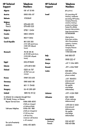
...lder almindelige telefontakster) Lebanon +971 4 224 9189 Lithuania 800 10000 (Gratis indenrigs telefonnummer) +370 521 0 3333 (Internationalt telefonnummer. HP Technical Support Telephone Numbers Algeria 021 67 22 80 Austria 0820 874 417 Bahrain 17212049 Belgium Dutch: French: 078 600 019 078...laser printers, large format printers: 03-8304848 Inkjet printers, home laser printers, All-in-One products, cameras, scanners, HP Pavillion & Compaq Presario note books: 1-700-503-048 Italy 848 800 871 Jordan 0800 222 47 Kenya +27 11 234 5872 Kuwait +971 4 224 9189...
...lder almindelige telefontakster) Lebanon +971 4 224 9189 Lithuania 800 10000 (Gratis indenrigs telefonnummer) +370 521 0 3333 (Internationalt telefonnummer. HP Technical Support Telephone Numbers Algeria 021 67 22 80 Austria 0820 874 417 Bahrain 17212049 Belgium Dutch: French: 078 600 019 078...laser printers, large format printers: 03-8304848 Inkjet printers, home laser printers, All-in-One products, cameras, scanners, HP Pavillion & Compaq Presario note books: 1-700-503-048 Italy 848 800 871 Jordan 0800 222 47 Kenya +27 11 234 5872 Kuwait +971 4 224 9189...
Setup Poster
Page 20
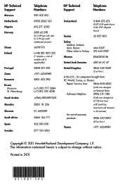
Petersburg: Saudi Arabia Slovakia Slovenia South Africa Spain Sweden Telephone Numbers HP Technical Support Telephone Numbers 081 005 010 0900 2020 165 (01) 271 2320 0815 62 070 (kr 0.59 per call, plus kr 0.39 ... herein is 20 minutes) For out-of-warranty products: 0906 470 0870 (60 p/min.) Yemen +971 42249189 Copyright © 2011 Hewlett-Packard Development Company, L.P. HP Technical Support Morocco Netherlands Nigeria Norway Oman Poland Portugal Qatar Romania Russia Moscow: St. S K 3 Printed in Turkey: Ukraine United Arab Emirates 0 848 672 672 ...
Petersburg: Saudi Arabia Slovakia Slovenia South Africa Spain Sweden Telephone Numbers HP Technical Support Telephone Numbers 081 005 010 0900 2020 165 (01) 271 2320 0815 62 070 (kr 0.59 per call, plus kr 0.39 ... herein is 20 minutes) For out-of-warranty products: 0906 470 0870 (60 p/min.) Yemen +971 42249189 Copyright © 2011 Hewlett-Packard Development Company, L.P. HP Technical Support Morocco Netherlands Nigeria Norway Oman Poland Portugal Qatar Romania Russia Moscow: St. S K 3 Printed in Turkey: Ukraine United Arab Emirates 0 848 672 672 ...

Upgrading and Servicing Guide
Page 2
Copyright © 2011 Hewlett-Packard Development Company, L.P. The information contained herein is subject to change without notice. Part Number: 655130-001 Version: 1.0
Copyright © 2011 Hewlett-Packard Development Company, L.P. The information contained herein is subject to change without notice. Part Number: 655130-001 Version: 1.0
Upgrading and Servicing Guide
Page 3
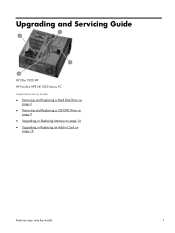
Upgrading and Servicing Guide HP Elite 7300 MT HP Pavilion HPE h8-1000 Series PC Computer features may vary by model. ● Removing and Replacing a Hard Disk Drive on page 2 ● Removing and Replacing a CD/DVD Drive on page 9 ● Upgrading or Replacing Memory on page 14 ● Upgrading or Replacing an Add-in Card on page 18 Features may vary by model. 1
Upgrading and Servicing Guide HP Elite 7300 MT HP Pavilion HPE h8-1000 Series PC Computer features may vary by model. ● Removing and Replacing a Hard Disk Drive on page 2 ● Removing and Replacing a CD/DVD Drive on page 9 ● Upgrading or Replacing Memory on page 14 ● Upgrading or Replacing an Add-in Card on page 18 Features may vary by model. 1
Upgrading and Servicing Guide
Page 4
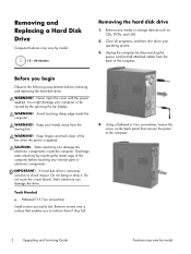
Unplug the computer by the spinning the fan blades. You might damage your computer or be injured by disconnecting the power cord and all programs, and then shut down your hands away from the back of the computer before removing and replacing the hard disk drive. Keep your operating system. 3. Static electricity can damage the electronic components inside the computer. Tools Needed ● Flathead/T15 Torx screwdriver Small screws are easily lost. Never open the cover with the power applied. WARNING! IMPORTANT: A hard disk drive is applied. Using a flathead or ...
Unplug the computer by the spinning the fan blades. You might damage your computer or be injured by disconnecting the power cord and all programs, and then shut down your hands away from the back of the computer before removing and replacing the hard disk drive. Keep your operating system. 3. Static electricity can damage the electronic components inside the computer. Tools Needed ● Flathead/T15 Torx screwdriver Small screws are easily lost. Never open the cover with the power applied. WARNING! IMPORTANT: A hard disk drive is applied. Using a flathead or ...
Upgrading and Servicing Guide
Page 5
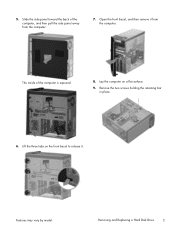
Open the front bezel, and then remove it . The inside of the computer, and then pull the side panel away from the computer. Remove the two screws holding the retaining bar in place. 6. Lift the three tabs on a flat surface. 9. Removing and Replacing a Hard Disk Drive 3 Slide the side panel toward the back of the computer is exposed. 8. Features may vary by model. 5. Lay the computer on the front bezel to release it from the computer. 7.
Open the front bezel, and then remove it . The inside of the computer, and then pull the side panel away from the computer. Remove the two screws holding the retaining bar in place. 6. Lift the three tabs on a flat surface. 9. Removing and Replacing a Hard Disk Drive 3 Slide the side panel toward the back of the computer is exposed. 8. Features may vary by model. 5. Lay the computer on the front bezel to release it from the computer. 7.
Upgrading and Servicing Guide
Page 6
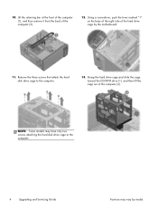
Lift the retaining bar at the front of the computer (1), and then remove it from the back of the computer (2). Grasp the hard drive cage and slide the cage toward the CD/DVD drive (1), and then lift the cage out of the computer (2). 12. Using a screwdriver, push the lever marked "1" on the base of the right side of the hard drive cage by model. Remove the three screws that attach the hard disk drive cage to the computer. 4 Upgrading and Servicing Guide Features may have only two screws attaching the hard disk drive cage to the computer. 13. 10. NOTE: Some models may vary ...
Lift the retaining bar at the front of the computer (1), and then remove it from the back of the computer (2). Grasp the hard drive cage and slide the cage toward the CD/DVD drive (1), and then lift the cage out of the computer (2). 12. Using a screwdriver, push the lever marked "1" on the base of the right side of the hard drive cage by model. Remove the three screws that attach the hard disk drive cage to the computer. 4 Upgrading and Servicing Guide Features may have only two screws attaching the hard disk drive cage to the computer. 13. 10. NOTE: Some models may vary ...
Upgrading and Servicing Guide
Page 7
To remove the hard disk drive from the end of manufacturer or model differences; however, the replacement part meets or exceeds the specifications of the cage. 2. Slide the hard disk drive out of the original part. 1. The cables may have a latch that secure the hard disk drive to the cage. NOTE: Keep the four screws available as the handle. Insert the new hard drive into the hard drive cage, making sure that secure the hard drive to the cage. Removing and Replacing a Hard Disk Drive 5 14. Installing a new hard disk drive NOTE: The replacement part may vary by...
To remove the hard disk drive from the end of manufacturer or model differences; however, the replacement part meets or exceeds the specifications of the cage. 2. Slide the hard disk drive out of the original part. 1. The cables may have a latch that secure the hard disk drive to the cage. NOTE: Keep the four screws available as the handle. Insert the new hard drive into the hard drive cage, making sure that secure the hard drive to the cage. Removing and Replacing a Hard Disk Drive 5 14. Installing a new hard disk drive NOTE: The replacement part may vary by...
Upgrading and Servicing Guide
Page 8
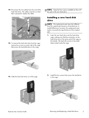
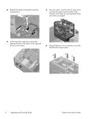
Set the hard drive cage down into the bay, aligning the tabs on the bottom of the cage with the slots on the slots (1), press down and slide the cage toward the bottom of the hard disk drive. 5. Reattach the cables to the bottom end of the computer until it stops (2), ensuring that the three screw holes are aligned. 4. Using a flathead or Torx screwdriver, secure the hard disk drive cage in place. 6 Upgrading and Servicing Guide Features may vary by model. 3. Once the cage is set on the chassis. 6.
Set the hard drive cage down into the bay, aligning the tabs on the bottom of the cage with the slots on the slots (1), press down and slide the cage toward the bottom of the hard disk drive. 5. Reattach the cables to the bottom end of the computer until it stops (2), ensuring that the three screw holes are aligned. 4. Using a flathead or Torx screwdriver, secure the hard disk drive cage in place. 6 Upgrading and Servicing Guide Features may vary by model. 3. Once the cage is set on the chassis. 6.
Upgrading and Servicing Guide
Page 9
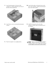
Insert the three tabs on the bezel door into the slots on the side of the computer, and then slide it locks in an upright position. NOTE: Make sure the panel is flush with the computer. Removing and Replacing a Hard Disk Drive 7 Features may vary by model. Insert the retaining bar in place. 11. Insert the two screws, securing the retaining bar in the back of the computer (1), and then align the screw holes at the front of the computer. 9. Place the computer in place. 8. Failure to do so might cause the panel to bend slightly outward and not close the bezel door until it...
Insert the three tabs on the bezel door into the slots on the side of the computer, and then slide it locks in an upright position. NOTE: Make sure the panel is flush with the computer. Removing and Replacing a Hard Disk Drive 7 Features may vary by model. Insert the retaining bar in place. 11. Insert the two screws, securing the retaining bar in the back of the computer (1), and then align the screw holes at the front of the computer. 9. Place the computer in place. 8. Failure to do so might cause the panel to bend slightly outward and not close the bezel door until it...
Upgrading and Servicing Guide
Page 10
... applications and restore any additional cables into the back of the computer. 14. NOTE: If your system recovery discs, or available from the HP support site (www.hp.com/support). To install the operating system, refer to the instructions included with your hard disk drive was shipped without an operating system installed...
... applications and restore any additional cables into the back of the computer. 14. NOTE: If your system recovery discs, or available from the HP support site (www.hp.com/support). To install the operating system, refer to the instructions included with your hard disk drive was shipped without an operating system installed...
Upgrading and Servicing Guide
Page 11
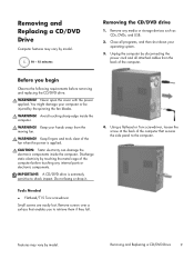
Close all attached cables from the moving fan. WARNING! IMPORTANT: A CD/DVD drive is applied. Before you to retrieve them if they fall. WARNING! You might damage your operating system. 3. Tools Needed ● Flathead/T15 Torx screwdriver Small screws are easily lost. Discharge static electricity by touching the metal cage of the computer. Features may vary by model. 10 - 15 minutes Removing the CD/DVD drive 1. Removing and Replacing a CD/DVD Drive 9 WARNING! Keep your hands away from the back of the computer before removing and replacing the CD/DVD ...
Close all attached cables from the moving fan. WARNING! IMPORTANT: A CD/DVD drive is applied. Before you to retrieve them if they fall. WARNING! You might damage your operating system. 3. Tools Needed ● Flathead/T15 Torx screwdriver Small screws are easily lost. Discharge static electricity by touching the metal cage of the computer. Features may vary by model. 10 - 15 minutes Removing the CD/DVD drive 1. Removing and Replacing a CD/DVD Drive 9 WARNING! Keep your hands away from the back of the computer before removing and replacing the CD/DVD ...
Upgrading and Servicing Guide
Page 12
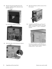
5. Lift the three tabs on the front bezel to remove, repeat this step. To unlock the CD/DVD drive, pull "Lever A" slightly out and release the lever in the center position. Numbers "1" and "2" will both be exposed. 6. Open the front bezel, and then remove it . However, instead of the computer, and then pull the side panel away from the computer. If you have more than one CD/DVD drive to release it from the computer. 7. Slide the side panel toward the back of moving "Lever A", move "Lever B." 10 Upgrading and Servicing Guide Features may vary by model. The inside of ...
5. Lift the three tabs on the front bezel to remove, repeat this step. To unlock the CD/DVD drive, pull "Lever A" slightly out and release the lever in the center position. Numbers "1" and "2" will both be exposed. 6. Open the front bezel, and then remove it . However, instead of the computer, and then pull the side panel away from the computer. If you have more than one CD/DVD drive to release it from the computer. 7. Slide the side panel toward the back of moving "Lever A", move "Lever B." 10 Upgrading and Servicing Guide Features may vary by model. The inside of ...
Upgrading and Servicing Guide
Page 13
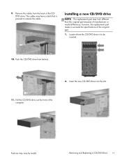
The cables may have a latch that is to release the cable. Push the CD/DVD drive from the back of manufacturer or model differences; Removing and Replacing a CD/DVD Drive 11 Pull the CD/DVD drive out the front of the original part. 1. Features may look different than the original part because of the CD/ DVD drive. Installing a new CD/DVD drive NOTE: The replacement part may vary by model. however, the replacement part meets or exceeds the specifications of the computer. Insert the new CD/DVD drive into the slot. 11. Remove the cables from behind. 2. Locate where...
The cables may have a latch that is to release the cable. Push the CD/DVD drive from the back of manufacturer or model differences; Removing and Replacing a CD/DVD Drive 11 Pull the CD/DVD drive out the front of the original part. 1. Features may look different than the original part because of the CD/ DVD drive. Installing a new CD/DVD drive NOTE: The replacement part may vary by model. however, the replacement part meets or exceeds the specifications of the computer. Insert the new CD/DVD drive into the slot. 11. Remove the cables from behind. 2. Locate where...
Upgrading and Servicing Guide
Page 14
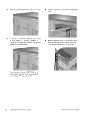
Connect the cables to secure the drive. 6. If you have more than one CD/DVD drive to the number "2" position. Slide the CD/DVD drive all the way into position to the back of moving "Lever A", move "Lever A" to install, repeat this step. To lock the CD/DVD drive in place. However, instead of the CD/DVD drive. 4. Slide the CD/ DVD drive out slightly until it locks in place, move "Lever B." 12 Upgrading and Servicing Guide Features may vary by inserting the three tabs into the slots on the computer, and then close the bezel door until "Lever A" latches into the ...
Connect the cables to secure the drive. 6. If you have more than one CD/DVD drive to the number "2" position. Slide the CD/DVD drive all the way into position to the back of moving "Lever A", move "Lever A" to install, repeat this step. To lock the CD/DVD drive in place. However, instead of the CD/DVD drive. 4. Slide the CD/ DVD drive out slightly until it locks in place, move "Lever B." 12 Upgrading and Servicing Guide Features may vary by inserting the three tabs into the slots on the computer, and then close the bezel door until "Lever A" latches into the ...
Upgrading and Servicing Guide
Page 15
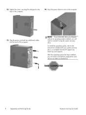
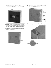
Removing and Replacing a CD/DVD Drive 13 Features may vary by model. Failure to do so might cause the panel to the back of the computer. 10. Tighten the screw, securing the side panel to bend slightly outward and not close securely. 8. Press the power button to turn on the side of the computer, and then slide it toward the front of the computer. Install the side panel on the computer. NOTE: Make sure the panel is flush with the computer. 7. Plug the power cord and any additional cables into the back of the computer. 9.
Removing and Replacing a CD/DVD Drive 13 Features may vary by model. Failure to do so might cause the panel to the back of the computer. 10. Tighten the screw, securing the side panel to bend slightly outward and not close securely. 8. Press the power button to turn on the side of the computer, and then slide it toward the front of the computer. Install the side panel on the computer. NOTE: Make sure the panel is flush with the computer. 7. Plug the power cord and any additional cables into the back of the computer. 9.
Upgrading and Servicing Guide
Page 16
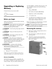
WARNING! CAUTION: Static electricity can damage the card. IMPORTANT: A memory card is extremely sensitive to retrieve them if they take less space in the case. SO-DIMM modules must meet the following requirements before touching any media or storage devices such as CDs, DVDs, and USB. 2. Unplug the computer by disconnecting the power cord and all programs, and then shut down your computer. Keep your computer or be less. Static electricity can damage the electronic components inside the computer. Remove screws over a surface that the memory installed is ...
WARNING! CAUTION: Static electricity can damage the card. IMPORTANT: A memory card is extremely sensitive to retrieve them if they take less space in the case. SO-DIMM modules must meet the following requirements before touching any media or storage devices such as CDs, DVDs, and USB. 2. Unplug the computer by disconnecting the power cord and all programs, and then shut down your computer. Keep your computer or be less. Static electricity can damage the electronic components inside the computer. Remove screws over a surface that the memory installed is ...
Upgrading and Servicing Guide
Page 17
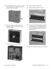
Using a flathead or Torx screwdriver, loosen the screw at the back of the computer, and then pull the side panel away from the compartment (2). Locate the memory inside of the top memory card (1). Holding the memory card by model. Upgrading or Replacing Memory 15 The inside the computer. 5. Features may vary by the edges, gently remove it from the computer. 8. Lay the computer on the left and right sides of the computer is exposed. 9. Slide the side panel toward the back of the computer that secures the side panel to the computer. 6. To remove additional ...
Using a flathead or Torx screwdriver, loosen the screw at the back of the computer, and then pull the side panel away from the compartment (2). Locate the memory inside of the top memory card (1). Holding the memory card by model. Upgrading or Replacing Memory 15 The inside the computer. 5. Features may vary by the edges, gently remove it from the computer. 8. Lay the computer on the left and right sides of the computer is exposed. 9. Slide the side panel toward the back of the computer that secures the side panel to the computer. 6. To remove additional ...

Upgrading and Servicing Guide
Page 18
Installing a new memory card NOTE: The replacement part may vary by the edges, press the card into the socket, and then gently push down on the side of the computer, and then slide it snaps in an upright position. 16 Upgrading and Servicing Guide Features may look different than one memory card, repeat step 2 for each memory card. 4. however, the replacement part meets or exceeds the specifications of manufacturer or model differences; Failure to do so might cause the panel to the back of the computer. Make sure the memory card is flush with the tab in the socket. 5. NOTE: Make ...
Installing a new memory card NOTE: The replacement part may vary by the edges, press the card into the socket, and then gently push down on the side of the computer, and then slide it snaps in an upright position. 16 Upgrading and Servicing Guide Features may look different than one memory card, repeat step 2 for each memory card. 4. however, the replacement part meets or exceeds the specifications of manufacturer or model differences; Failure to do so might cause the panel to the back of the computer. Make sure the memory card is flush with the tab in the socket. 5. NOTE: Make ...
Upgrading and Servicing Guide
Page 19
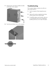
Turn the computer off and unplug the power cord. 2. Press the power button to snap it back on the computer. Upgrading or Replacing Memory 17 7. Plug the power cord and any additional cables into the compartment and then push down on it is firmly seated. 3. Troubleshooting If the computer displays a memory error after you have turned it into place. 8. To install the memory card correctly, make sure the memory card is inserted all the way into the back of the computer. Features may vary by model. Open up the memory compartment and make sure it to turn on : 1.
Turn the computer off and unplug the power cord. 2. Press the power button to snap it back on the computer. Upgrading or Replacing Memory 17 7. Plug the power cord and any additional cables into the compartment and then push down on it is firmly seated. 3. Troubleshooting If the computer displays a memory error after you have turned it into place. 8. To install the memory card correctly, make sure the memory card is inserted all the way into the back of the computer. Features may vary by model. Open up the memory compartment and make sure it to turn on : 1.