
Service Manual
Page 10
...Remove the hard drive and SATA cable 195 Fax PCA and cable ...197 Remove the fax PCA and cable 197 Tray cassette ...199 Fuser ...200 Pickup roller (Tray 2) ...201 Pickup and feed rollers (Tray 3 203 Separation roller (Tray 2 204 Secondary transfer roller ... assembly 207 Reinstall the secondary transfer assembly 208 Intermediate transfer belt (ITB 209 Front-door assembly ...211 Automatic document feeder (ADF 212 Calibrate a replacement ADF assembly 214 ADF roller assembly and separation pad 215 Reinstall the ADF roller assembly 217 Control-panel overlay ...218 Control-panel assembly ...
...Remove the hard drive and SATA cable 195 Fax PCA and cable ...197 Remove the fax PCA and cable 197 Tray cassette ...199 Fuser ...200 Pickup roller (Tray 2) ...201 Pickup and feed rollers (Tray 3 203 Separation roller (Tray 2 204 Secondary transfer roller ... assembly 207 Reinstall the secondary transfer assembly 208 Intermediate transfer belt (ITB 209 Front-door assembly ...211 Automatic document feeder (ADF 212 Calibrate a replacement ADF assembly 214 ADF roller assembly and separation pad 215 Reinstall the ADF roller assembly 217 Control-panel overlay ...218 Control-panel assembly ...

Service Manual
Page 12
... motor 313 Lifter-drive assembly ...314 Remove the lifter-drive assembly 314 Cassette-pickup drive assembly 316 Remove the cassette-pickup drive assembly 316 Reinstall the cassette-pickup drive assembly 321 Cassette-pickup assembly 323 Remove the cassette-pickup assembly 323 Laser/scanner assembly (Y/M 325 Remove the laser/scanner assembly (Y/M 325 Laser/scanner assembly (C/Bk 332 Remove the laser/scanner assembly (C/Bk 332 Reinstall the...
... motor 313 Lifter-drive assembly ...314 Remove the lifter-drive assembly 314 Cassette-pickup drive assembly 316 Remove the cassette-pickup drive assembly 316 Reinstall the cassette-pickup drive assembly 321 Cassette-pickup assembly 323 Remove the cassette-pickup assembly 323 Laser/scanner assembly (Y/M 325 Remove the laser/scanner assembly (Y/M 325 Laser/scanner assembly (C/Bk 332 Remove the laser/scanner assembly (C/Bk 332 Reinstall the...
Service Manual
Page 15
... ...515 Service manuals and user documentation 518 Screws ...519 How to use the parts lists and diagrams 519 ADF and scanner assemblies ...520 External covers, panels, and doors 522 Right door assembly ...524 Internal components ...526 Internal components (1 of 5 526 Internal components (2 of 5 528 Internal components (3 of 5 530 Internal components (4 of 5 532...
... ...515 Service manuals and user documentation 518 Screws ...519 How to use the parts lists and diagrams 519 ADF and scanner assemblies ...520 External covers, panels, and doors 522 Right door assembly ...524 Internal components ...526 Internal components (1 of 5 526 Internal components (2 of 5 528 Internal components (3 of 5 530 Internal components (4 of 5 532...
Service Manual
Page 16
...assembly 540 Registration assembly ...542 Paper-delivery assembly 544 PCAs ...546 Formatter components ...548 Accessories ...550 500-sheet paper feeder 550 Paper feeder main body 552 Alphabetical parts list ...554 Numerical parts list ...561 Appendix A Service and support Hewlett-Packard limited warranty statement 570 Print cartridge limited warranty statement 571 HP Color LaserJet Fuser...583 Safety statements ...584 Laser safety ...584 Canadian DOC regulations 584 VCCI statement (Japan 584 Power cord statement (Japan 584 EMC statement (Korea 584 Laser statement for Finland 584 ...
...assembly 540 Registration assembly ...542 Paper-delivery assembly 544 PCAs ...546 Formatter components ...548 Accessories ...550 500-sheet paper feeder 550 Paper feeder main body 552 Alphabetical parts list ...554 Numerical parts list ...561 Appendix A Service and support Hewlett-Packard limited warranty statement 570 Print cartridge limited warranty statement 571 HP Color LaserJet Fuser...583 Safety statements ...584 Laser safety ...584 Canadian DOC regulations 584 VCCI statement (Japan 584 Power cord statement (Japan 584 EMC statement (Korea 584 Laser statement for Finland 584 ...
Service Manual
Page 18
... 8-15 Internal components (4 of 5) ...533 Table 8-16 Internal components (5 of 5) ...535 Table 8-17 Fuser ...537 Table 8-18 250-sheet cassette ...539 Table 8-19 250-sheet cassette paper pickup assembly 541 Table 8-20 Registration assembly ...543 Table 8-21 Paper-delivery assembly ...545 Table 8-22 PCAs ...547 Table 8-23 Formatter components ...549 Table 8-24 500-sheet...
... 8-15 Internal components (4 of 5) ...533 Table 8-16 Internal components (5 of 5) ...535 Table 8-17 Fuser ...537 Table 8-18 250-sheet cassette ...539 Table 8-19 250-sheet cassette paper pickup assembly 541 Table 8-20 Registration assembly ...543 Table 8-21 Paper-delivery assembly ...545 Table 8-22 PCAs ...547 Table 8-23 Formatter components ...549 Table 8-24 500-sheet...
Service Manual
Page 23
... 6-58 Figure 6-59 Figure 6-60 Figure 6-61 Figure 6-62 Figure 6-63 Figure 6-64 Figure 6-65 Figure 6-66 Figure 6-67 Figure 6-68 Remove the fuser (2 of 2) ...200 Remove the pickup roller (Tray 2) (1 of 4 201 Remove the pickup roller (Tray 2) (2 of 4 201 Remove the pickup ... Reinstall the transfer roller ...206 Remove the transfer roller (2 of 3 207 Remove the secondary transfer assembly (1 of 2 207 Remove the secondary transfer assembly (2 of 2 208 Reinstall the secondary transfer assembly 208 Remove the intermediate transfer belt (1 of 3 209 Remove the intermediate transfer belt (2 of 3...
... 6-58 Figure 6-59 Figure 6-60 Figure 6-61 Figure 6-62 Figure 6-63 Figure 6-64 Figure 6-65 Figure 6-66 Figure 6-67 Figure 6-68 Remove the fuser (2 of 2) ...200 Remove the pickup roller (Tray 2) (1 of 4 201 Remove the pickup roller (Tray 2) (2 of 4 201 Remove the pickup ... Reinstall the transfer roller ...206 Remove the transfer roller (2 of 3 207 Remove the secondary transfer assembly (1 of 2 207 Remove the secondary transfer assembly (2 of 2 208 Reinstall the secondary transfer assembly 208 Remove the intermediate transfer belt (1 of 3 209 Remove the intermediate transfer belt (2 of 3...
Service Manual
Page 28
... the main-drive assembly (10 of 11 354 Reinstall the main-drive assembly (11 of 11 355 Remove the fuser-drive assembly (1 of 6 357 Remove the fuser-drive assembly (2 of 6 357 Remove the fuser-drive assembly (3 of 6 358 Remove the fuser-drive assembly (4 of 6 358 Remove the fuser-drive assembly (5 of 6 359 Remove the fuser-drive assembly (6 of 6 359 Reinstall the fuser-drive assembly 360 xxvi...
... the main-drive assembly (10 of 11 354 Reinstall the main-drive assembly (11 of 11 355 Remove the fuser-drive assembly (1 of 6 357 Remove the fuser-drive assembly (2 of 6 357 Remove the fuser-drive assembly (3 of 6 358 Remove the fuser-drive assembly (4 of 6 358 Remove the fuser-drive assembly (5 of 6 359 Remove the fuser-drive assembly (6 of 6 359 Reinstall the fuser-drive assembly 360 xxvi...
Service Manual
Page 29
... Remove the delivery assembly (1 of 5 362 Figure 6-290 Remove the delivery assembly (2 of 5 362 Figure 6-291 Remove the delivery assembly (3 of 5 363 Figure 6-292 Remove the delivery assembly (4 of 5 363 Figure 6-293 Remove the delivery assembly (5 of 5 364 Figure 6-294 Reinstall the delivery assembly (1 of 2 ...button ...386 Figure 7-4 Test the TOP sensor ...389 Figure 7-5 Test the loop sensors ...390 Figure 7-6 Test the fuser delivery sensor (1 of 2 391 Figure 7-7 Test the fuser (fixing) delivery sensor (2 of 2 391 Figure 7-8 Test the duplex re-pickup sensor 392 Figure 7-9 Test the ...
... Remove the delivery assembly (1 of 5 362 Figure 6-290 Remove the delivery assembly (2 of 5 362 Figure 6-291 Remove the delivery assembly (3 of 5 363 Figure 6-292 Remove the delivery assembly (4 of 5 363 Figure 6-293 Remove the delivery assembly (5 of 5 364 Figure 6-294 Reinstall the delivery assembly (1 of 2 ...button ...386 Figure 7-4 Test the TOP sensor ...389 Figure 7-5 Test the loop sensors ...390 Figure 7-6 Test the fuser delivery sensor (1 of 2 391 Figure 7-7 Test the fuser (fixing) delivery sensor (2 of 2 391 Figure 7-8 Test the duplex re-pickup sensor 392 Figure 7-9 Test the ...

Service Manual
Page 30
...page ...436 Figure 7-48 HP embedded Jetdirect page ...438 Figure 7-49 Embedded protocol page ...439 Figure 7-50 Jam locations ...473 Figure 8-1 ADF/scanner assembly ...520 Figure 8-2 External covers, panels, and doors 522 Figure 8-3 Right door assembly ...524 Figure 8-4 Internal ...532 Figure 8-8 Internal components (5 of 5) ...534 Figure 8-9 Fuser ...536 Figure 8-10 250-sheet cassette ...538 Figure 8-11 250-sheet cassette paper pickup assembly 540 Figure 8-12 Registration assembly ...542 Figure 8-13 Paper-delivery assembly ...544 Figure 8-14 PCAs ...546 Figure 8-15 Formatter components...
...page ...436 Figure 7-48 HP embedded Jetdirect page ...438 Figure 7-49 Embedded protocol page ...439 Figure 7-50 Jam locations ...473 Figure 8-1 ADF/scanner assembly ...520 Figure 8-2 External covers, panels, and doors 522 Figure 8-3 Right door assembly ...524 Figure 8-4 Internal ...532 Figure 8-8 Internal components (5 of 5) ...534 Figure 8-9 Fuser ...536 Figure 8-10 250-sheet cassette ...538 Figure 8-11 250-sheet cassette paper pickup assembly 540 Figure 8-12 Registration assembly ...542 Figure 8-13 Paper-delivery assembly ...544 Figure 8-14 PCAs ...546 Figure 8-15 Formatter components...
Service Manual
Page 230
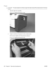
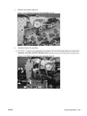
Figure 6-24 Remove the fuser (1 of 2) 200 Chapter 6 Removal and replacement ENWW Figure 6-25 Remove the fuser (2 of 2) 2. Allow enough time after turning off the product power for the fuser to remove it. Open the right-door assembly. Pull the fuser straight out of the product to cool. 1. Grasp the handles and squeeze the blue release levers. Fuser CAUTION: The fuser might be hot.
Figure 6-24 Remove the fuser (1 of 2) 200 Chapter 6 Removal and replacement ENWW Figure 6-25 Remove the fuser (2 of 2) 2. Allow enough time after turning off the product power for the fuser to remove it. Open the right-door assembly. Pull the fuser straight out of the product to cool. 1. Grasp the handles and squeeze the blue release levers. Fuser CAUTION: The fuser might be hot.
Service Manual
Page 375
.... See DC controller PCA and tray on page 233. ● Rear-upper cover. Fuser motor Before proceeding, remove the following components: ● Formatter PCA. Figure 6-263 Remove the fuser motor 1 2 ENWW Internal assemblies 345 See Left cover on page 270. ● Low-voltage power supply (LVPS)....DC controller PCA and tray. See High-voltage power supply upper on page 267. See Interconnect board (ICB) on page 339. Remove the fuser motor Disconnect one connector (callout 1), remove three screws (callout 2), and then remove the motor. See Rear cover on page 192 ●...
.... See DC controller PCA and tray on page 233. ● Rear-upper cover. Fuser motor Before proceeding, remove the following components: ● Formatter PCA. Figure 6-263 Remove the fuser motor 1 2 ENWW Internal assemblies 345 See Left cover on page 270. ● Low-voltage power supply (LVPS)....DC controller PCA and tray. See High-voltage power supply upper on page 267. See Interconnect board (ICB) on page 339. Remove the fuser motor Disconnect one connector (callout 1), remove three screws (callout 2), and then remove the motor. See Rear cover on page 192 ●...
Service Manual
Page 386
.... ● Low-voltage power supply (LVPS). See Fuser on page 225 ● Right-rear cover. See Front-upper cover on page 200. ● Secondary transfer assembly. See Scanner assembly on page 339. ● Main-drive assembly. See High-voltage power supply upper on page 242.... ● Front-top cover. Fuser-drive assembly Before proceeding, remove the following components: ● Formatter PCA. ...
.... ● Low-voltage power supply (LVPS). See Fuser on page 225 ● Right-rear cover. See Front-upper cover on page 200. ● Secondary transfer assembly. See Scanner assembly on page 339. ● Main-drive assembly. See High-voltage power supply upper on page 242.... ● Front-top cover. Fuser-drive assembly Before proceeding, remove the following components: ● Formatter PCA. ...
Service Manual
Page 387
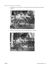
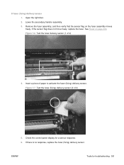
Disconnect one connector (callout 1), and then release the wire harnesses from the guide (callout 2). Figure 6-282 Remove the fuser-drive assembly (1 of 6) 3 4 ENWW Internal assemblies 357 Figure 6-283 Remove the fuser-drive assembly (2 of 6) 2 1 2. Remove two screws (callout 3), and then remove the guide (callout 4). Remove the fuser-drive assembly 1.
Disconnect one connector (callout 1), and then release the wire harnesses from the guide (callout 2). Figure 6-282 Remove the fuser-drive assembly (1 of 6) 3 4 ENWW Internal assemblies 357 Figure 6-283 Remove the fuser-drive assembly (2 of 6) 2 1 2. Remove two screws (callout 3), and then remove the guide (callout 4). Remove the fuser-drive assembly 1.
Service Manual
Page 388
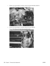
Remove one screw (callout 5), and then remove the sheet-metal plate (callout 6). Figure 6-285 Remove the fuser-drive assembly (4 of 6) 6 5 4. Remove one screw (callout 7), and then remove the cover (callout 8). Figure 6-284 Remove the fuser-drive assembly (3 of 6) 8 7 358 Chapter 6 Removal and replacement ENWW 3.
Remove one screw (callout 5), and then remove the sheet-metal plate (callout 6). Figure 6-285 Remove the fuser-drive assembly (4 of 6) 6 5 4. Remove one screw (callout 7), and then remove the cover (callout 8). Figure 6-284 Remove the fuser-drive assembly (3 of 6) 8 7 358 Chapter 6 Removal and replacement ENWW 3.
Service Manual
Page 389
Figure 6-287 Remove the fuser-drive assembly (6 of 6) 9 6. Remove five screws (callout 9). Do not lose the gear when you remove the assembly. If the gear becomes dislodged, see Reinstall the fuser-drive assembly on the assembly is not captive. 5. Carefully remove the assembly. CAUTION: A gear on page 360. Figure 6-286 Remove the fuser-drive assembly (5 of 6) ENWW Internal assemblies 359
Figure 6-287 Remove the fuser-drive assembly (6 of 6) 9 6. Remove five screws (callout 9). Do not lose the gear when you remove the assembly. If the gear becomes dislodged, see Reinstall the fuser-drive assembly on the assembly is not captive. 5. Carefully remove the assembly. CAUTION: A gear on page 360. Figure 6-286 Remove the fuser-drive assembly (5 of 6) ENWW Internal assemblies 359
Service Manual
Page 390
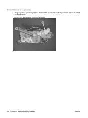
Reinstall the fuser-drive assembly If the gear (callout 1) is dislodged when the assembly is removed, use the figure below to correctly install it on the assembly. Figure 6-288 Reinstall the fuser-drive assembly 1 360 Chapter 6 Removal and replacement ENWW
Reinstall the fuser-drive assembly If the gear (callout 1) is dislodged when the assembly is removed, use the figure below to correctly install it on the assembly. Figure 6-288 Reinstall the fuser-drive assembly 1 360 Chapter 6 Removal and replacement ENWW
Service Manual
Page 391
... ● Power-supply fan and fan duct. See Low-voltage power supply (LVPS) on page 262 ● Interconnect board (ICB). See Fuser-drive assembly on page 267. ● DC controller PCA. See Interconnect board (ICB) on page 356. See Front-upper cover on page 339. &#...9679; Main-drive assembly. See High-voltage power supply upper on page 225 ● Right-rear cover. Delivery assembly Before proceeding, remove the following components: ● Fuser. See Rear cover on page 300. ● High-voltage power supply lower...
... ● Power-supply fan and fan duct. See Low-voltage power supply (LVPS) on page 262 ● Interconnect board (ICB). See Fuser-drive assembly on page 267. ● DC controller PCA. See Interconnect board (ICB) on page 356. See Front-upper cover on page 339. &#...9679; Main-drive assembly. See High-voltage power supply upper on page 225 ● Right-rear cover. Delivery assembly Before proceeding, remove the following components: ● Fuser. See Rear cover on page 300. ● High-voltage power supply lower...
Service Manual
Page 396
...fan duct. See Low-voltage power supply (LVPS) on page 242. ● Front-top cover. See Main-drive assembly on page 356. ● Delivery assembly. See Fuser-drive assembly on page 346. ● Fuser-drive assembly. See Intermediate transfer belt (ITB) on page 231. ● Left cover. See Right-rear cover on page 209... board (ICB) on page 233. ● Rear-upper cover. See Power-supply fan and fan duct on page 200. ● Secondary transfer assembly. See Fuser on page 300. ● High-voltage power supply lower. See DC controller PCA and tray on page 339. ● Main-drive...
...fan duct. See Low-voltage power supply (LVPS) on page 242. ● Front-top cover. See Main-drive assembly on page 356. ● Delivery assembly. See Fuser-drive assembly on page 346. ● Fuser-drive assembly. See Intermediate transfer belt (ITB) on page 231. ● Left cover. See Right-rear cover on page 209... board (ICB) on page 233. ● Rear-upper cover. See Power-supply fan and fan duct on page 200. ● Secondary transfer assembly. See Fuser on page 300. ● High-voltage power supply lower. See DC controller PCA and tray on page 339. ● Main-drive...
Service Manual
Page 421
... sensor flag does not move freely, replace the fuser. See Fuser on the fuser assembly moves freely. Check the control-panel display for troubleshooting 391 Open the right door. 2. D fuser (fixing) delivery sensor 1. Lower the secondary transfer assembly. 3. Figure 7-6 Test the fuser delivery sensor (1 of paper to activate the fuser (fixing) delivery sensor. Insert a piece of 2) 4. If there...
... sensor flag does not move freely, replace the fuser. See Fuser on the fuser assembly moves freely. Check the control-panel display for troubleshooting 391 Open the right door. 2. D fuser (fixing) delivery sensor 1. Lower the secondary transfer assembly. 3. Figure 7-6 Test the fuser delivery sensor (1 of paper to activate the fuser (fixing) delivery sensor. Insert a piece of 2) 4. If there...
Service Manual
Page 547
...assembly installation instructions Fuser cleaning kit (letter) 50 sheets of HP Tough Paper Cleaning instructions Fuser kit (Maintenance kit) 110V service fuser kit ● Fuser assembly, 110V ● Fuser installation instructions ● Recycle flyer ● Return label 220V service fuser kit ● Fuser assembly, 220V ● Fuser...kit 250-sheet tray paper pickup roller Paper feed roller assembly (500 SF) Paper pickup roller (500 SF) Replacement and installation instructions Laser/scanner assembly kit Laser/scanner assembly Part number CC468-67919 ● Part number: CC519...
...assembly installation instructions Fuser cleaning kit (letter) 50 sheets of HP Tough Paper Cleaning instructions Fuser kit (Maintenance kit) 110V service fuser kit ● Fuser assembly, 110V ● Fuser installation instructions ● Recycle flyer ● Return label 220V service fuser kit ● Fuser assembly, 220V ● Fuser...kit 250-sheet tray paper pickup roller Paper feed roller assembly (500 SF) Paper pickup roller (500 SF) Replacement and installation instructions Laser/scanner assembly kit Laser/scanner assembly Part number CC468-67919 ● Part number: CC519...


