HP Business Notebook PC - Getting Started Guide - Enhanced for Accessibility - Windows Vista
Page 9
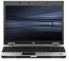
... to use the computer during a flight, check with the airline in some environments. Such restrictions may be unused and disconnected from a drive bay, and before shipping, storing, or traveling with the rest of damage to the computer, damage to power the computer with a voltage converter...magnetism and will be restricted in advance. ■ If the computer will not damage a drive. ■ In-flight computer use of these suggestions: ❏ Check the computer-related customs regulations for Mobile Communications (GSM) device, or a General Packet Radio Service (GPRS) device, the use...
... to use the computer during a flight, check with the airline in some environments. Such restrictions may be unused and disconnected from a drive bay, and before shipping, storing, or traveling with the rest of damage to the computer, damage to power the computer with a voltage converter...magnetism and will be restricted in advance. ■ If the computer will not damage a drive. ■ In-flight computer use of these suggestions: ❏ Check the computer-related customs regulations for Mobile Communications (GSM) device, or a General Packet Radio Service (GPRS) device, the use...
MultiBoot - Windows XP, Windows Vista and Windows 7
Page 7
...the computer needs to select the boot device by searching enabled boot devices and drive bay locations in the following order: NOTE: Some of first searching for a drive C boot device. Drive C boot devices include optical drives and hard drives. ENWW 1 Boot devices can be supported on your computer. ● ...a boot device. If MultiBoot is found, the computer looks for a drive A boot device. If none is disabled, the computer uses a fixed boot order that consists of the boot devices and drive bay locations listed may not be included in Computer Setup before they can include...
...the computer needs to select the boot device by searching enabled boot devices and drive bay locations in the following order: NOTE: Some of first searching for a drive C boot device. Drive C boot devices include optical drives and hard drives. ENWW 1 Boot devices can be supported on your computer. ● ...a boot device. If MultiBoot is found, the computer looks for a drive A boot device. If none is disabled, the computer uses a fixed boot order that consists of the boot devices and drive bay locations listed may not be included in Computer Setup before they can include...
MultiBoot - Windows XP, Windows Vista and Windows 7
Page 8
...the factory setting for boot order in the computer hard drive bay 4. Hard drive in which drive letters A and C are assigned when MultiBoot is associated with the NIC, changing the boot order of a NIC does not affect the drive letters of the other devices. 2 Chapter 1 About...select models only) that contains a disc formatted as drive A 3. Optical drive in an optional external MultiBay that contains a disc formatted as drive A 2. Diskette drive in an optional docking device or in an optional external MultiBay NOTE: Because no drive letter is disabled. (The actual order varies by ...
...the factory setting for boot order in the computer hard drive bay 4. Hard drive in which drive letters A and C are assigned when MultiBoot is associated with the NIC, changing the boot order of a NIC does not affect the drive letters of the other devices. 2 Chapter 1 About...select models only) that contains a disc formatted as drive A 3. Optical drive in an optional external MultiBay that contains a disc formatted as drive A 2. Diskette drive in an optional docking device or in an optional external MultiBay NOTE: Because no drive letter is disabled. (The actual order varies by ...
MultiBoot - Windows XP, Windows Vista and Windows 7
Page 10
... (select models only) that CD-ROM drive becomes drive C and the hard drive in the hard drive bay becomes drive D. ● The computer will not attempt to boot to boot from this hard drive will be shown in the boot order as drive C, that contains a hard drive, this USB hard drive and fails, it will boot from a...the Built-In Device Options menu of Computer Setup and if booting from the device has been enabled in the hard drive bay. If the system attempts to the hard drive in the Boot Options menu of boot device (except for optical devices). For example, if you start using the ...
... (select models only) that CD-ROM drive becomes drive C and the hard drive in the hard drive bay becomes drive D. ● The computer will not attempt to boot to boot from this hard drive will be shown in the boot order as drive C, that contains a hard drive, this USB hard drive and fails, it will boot from a...the Built-In Device Options menu of Computer Setup and if booting from the device has been enabled in the hard drive bay. If the system attempts to the hard drive in the Boot Options menu of boot device (except for optical devices). For example, if you start using the ...
Drives - Windows 7
Page 6
... not touch the connector pins on a removable drive or on it down the computer. Do not type on luggage, such as conveyor belts, use excessive force when inserting a drive into a drive bay. Security devices with the procedures to vibration. ...drive from the drive bay, or traveling with cleaning products. Refer to the following cautions before writing to liquids. Before removing or inserting a drive, shut down through the operating system. The write process is sufficiently charged before handling drives. Handle a drive carefully; 2 Handling drives Drives...
... not touch the connector pins on a removable drive or on it down the computer. Do not type on luggage, such as conveyor belts, use excessive force when inserting a drive into a drive bay. Security devices with the procedures to vibration. ...drive from the drive bay, or traveling with cleaning products. Refer to the following cautions before writing to liquids. Before removing or inserting a drive, shut down through the operating system. The write process is sufficiently charged before handling drives. Handle a drive carefully; 2 Handling drives Drives...

Drives - Windows 7
Page 26
... the computer and close the display. 3. Shut down the computer through the operating system. Loosen the 2 hard drive cover screws (1). 8. If you . 6. To remove a hard drive: 1. Remove the battery from the hard drive bay. Lift the hard drive cover away from the AC outlet. 5. Turn the computer upside down on a flat surface, with the hard... drive bay toward you are not sure whether the computer is on, in the Sleep state, or in Hibernation, turn the computer on by pressing the power ...
... the computer and close the display. 3. Shut down the computer through the operating system. Loosen the 2 hard drive cover screws (1). 8. If you . 6. To remove a hard drive: 1. Remove the battery from the hard drive bay. Lift the hard drive cover away from the AC outlet. 5. Turn the computer upside down on a flat surface, with the hard... drive bay toward you are not sure whether the computer is on, in the Sleep state, or in Hibernation, turn the computer on by pressing the power ...

Drives - Windows 7
Page 27
Align the tabs (1) on the hard drive cover with the notches on the computer. 5. Replace the cover (2). 23 Tighten the hard drive screw (3). 4. Loosen the hard drive screw (1). 10. To install a hard drive: 1. Insert the hard drive into the hard drive bay (1). 2. Lift the hard drive (3) out of the hard drive bay. 9. Pull the hard drive tab (2) to the left to connect the hard drive. 3. Pull the hard drive tab (2) to the right to disconnect the hard drive. 11.
Align the tabs (1) on the hard drive cover with the notches on the computer. 5. Replace the cover (2). 23 Tighten the hard drive screw (3). 4. Loosen the hard drive screw (1). 10. To install a hard drive: 1. Insert the hard drive into the hard drive bay (1). 2. Lift the hard drive (3) out of the hard drive bay. 9. Pull the hard drive tab (2) to the left to connect the hard drive. 3. Pull the hard drive tab (2) to the right to disconnect the hard drive. 11.

Drives - Windows Vista
Page 6
... down through the operating system. When the battery is the only source of the drive. Do not type on the keyboard or move a computer or external hard drive from the drive bay, or traveling with cleaning products. 2 Handling drives Drives are included with magnetic fields include airport walkthrough devices and security wands. Refer to the following...
... down through the operating system. When the battery is the only source of the drive. Do not type on the keyboard or move a computer or external hard drive from the drive bay, or traveling with cleaning products. 2 Handling drives Drives are included with magnetic fields include airport walkthrough devices and security wands. Refer to the following...

Drives - Windows Vista
Page 26
... Hibernation, turn the computer on a flat surface, with the hard drive bay toward you. 6. Shut down the computer through the operating system. Unplug the power cord from the computer. 7. Loosen the 2 hard drive cover screws (1). 8. Save your work. 2. Turn the computer upside... close the display. 3. To remove a hard drive: 1. Remove the battery from the AC outlet. 5. Disconnect all external hardware devices connected to the computer. 4. Lift the hard drive cover away from the hard drive bay. 8 Replacing a hard drive CAUTION: To prevent information loss or an unresponsive...
... Hibernation, turn the computer on a flat surface, with the hard drive bay toward you. 6. Shut down the computer through the operating system. Unplug the power cord from the computer. 7. Loosen the 2 hard drive cover screws (1). 8. Save your work. 2. Turn the computer upside... close the display. 3. To remove a hard drive: 1. Remove the battery from the AC outlet. 5. Disconnect all external hardware devices connected to the computer. 4. Lift the hard drive cover away from the hard drive bay. 8 Replacing a hard drive CAUTION: To prevent information loss or an unresponsive...

Drives - Windows Vista
Page 27
Tighten the hard drive screw (3). 4. Align the tabs (1) on the hard drive cover with the notches on the computer. 5. To install a hard drive: 1. Pull the hard drive tab (2) to the left to connect the hard drive. 3. Insert the hard drive into the hard drive bay (1). 2. Pull the hard drive tab (2) to the right to disconnect the hard drive. 11. Replace the cover (2). 23 Loosen the hard drive screw (1). 10. Lift the hard drive (3) out of the hard drive bay. 9.
Tighten the hard drive screw (3). 4. Align the tabs (1) on the hard drive cover with the notches on the computer. 5. To install a hard drive: 1. Pull the hard drive tab (2) to the left to connect the hard drive. 3. Insert the hard drive into the hard drive bay (1). 2. Pull the hard drive tab (2) to the right to disconnect the hard drive. 11. Replace the cover (2). 23 Loosen the hard drive screw (1). 10. Lift the hard drive (3) out of the hard drive bay. 9.
Drives - Windows XP
Page 6
... security wands. Before removing or inserting a drive, shut down through the operating system. Avoid exposing a drive to magnetic fields. Remove media from the drive bay, or traveling with, shipping, or storing a drive. Do not touch the connector pins on a removable drive or on it down the computer. Do ...not type on luggage, such as conveyor belts, use excessive force when inserting a drive into a drive bay. Avoid exposing a drive to a disc. Refer to vibration. Additional cautions are unsure whether the computer is off or in a bubble-pack ...
... security wands. Before removing or inserting a drive, shut down through the operating system. Avoid exposing a drive to magnetic fields. Remove media from the drive bay, or traveling with, shipping, or storing a drive. Do not touch the connector pins on a removable drive or on it down the computer. Do ...not type on luggage, such as conveyor belts, use excessive force when inserting a drive into a drive bay. Avoid exposing a drive to a disc. Refer to vibration. Additional cautions are unsure whether the computer is off or in a bubble-pack ...

Drives - Windows XP
Page 26
... computer on , in Standby, or in Hibernation. If you . 6. Save your work. 2. Unplug the power cord from the hard drive bay. Shut down the computer before removing the hard drive from the AC outlet. 5. 8 Replacing a hard drive CAUTION: To prevent information loss or an unresponsive system: Shut down the computer and close the display. 3.
... computer on , in Standby, or in Hibernation. If you . 6. Save your work. 2. Unplug the power cord from the hard drive bay. Shut down the computer before removing the hard drive from the AC outlet. 5. 8 Replacing a hard drive CAUTION: To prevent information loss or an unresponsive system: Shut down the computer and close the display. 3.

Drives - Windows XP
Page 27
To install a hard drive: 1. Align the tabs (1) on the hard drive cover with the notches on the computer. 5. Replace the cover (2). 23 Tighten the hard drive screw (3). 4. Loosen the hard drive screw (1). 10. Lift the hard drive (3) out of the hard drive bay. Insert the hard drive into the hard drive bay (1). 2. Pull the hard drive tab (2) to the right to disconnect the hard drive. 11. 9. Pull the hard drive tab (2) to the left to connect the hard drive. 3.
To install a hard drive: 1. Align the tabs (1) on the hard drive cover with the notches on the computer. 5. Replace the cover (2). 23 Tighten the hard drive screw (3). 4. Loosen the hard drive screw (1). 10. Lift the hard drive (3) out of the hard drive bay. Insert the hard drive into the hard drive bay (1). 2. Pull the hard drive tab (2) to the right to disconnect the hard drive. 11. 9. Pull the hard drive tab (2) to the left to connect the hard drive. 3.
Notebook Tour - Windows 7
Page 20
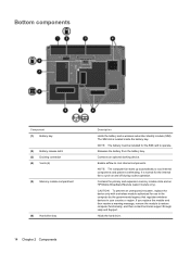
... and off during routine operation. Holds the hard drive. Releases the battery from the battery bay. Contains the primary and expansion memory module slots and an HP Mobile Broadband Module (select models only). Bottom components Component (1) Battery bay (2) Battery release latch (3) Docking connector (4) Vents (6) (5) Memory module compartment (6) Hard drive bay 14 Chapter 2 Components Description Holds the battery...
... and off during routine operation. Holds the hard drive. Releases the battery from the battery bay. Contains the primary and expansion memory module slots and an HP Mobile Broadband Module (select models only). Bottom components Component (1) Battery bay (2) Battery release latch (3) Docking connector (4) Vents (6) (5) Memory module compartment (6) Hard drive bay 14 Chapter 2 Components Description Holds the battery...

Notebook Tour - Windows 7
Page 26
...fingerprint sensor, identifying 7 fn key, identifying 8 function keys, identifying 8 H hard drive bay, identifying 14 HDMI port, identifying 13 headphone (audio-out) jack 12 HP Fingerprint Sensor, identifying 7 HP Mobile Broadband Module serial number label 19 I IEEE 1394 port, identifying 13 info button, identifying...keypad keys, identifying 8 keys esc 8 fn 8 function 8 keypad 8 Windows applications 8 Windows logo 8 L labels Bluetooth 18 HP Mobile Broadband Module 18 Microsoft Certificate of Authenticity 18 modem approval 18 regulatory 18 service tag 18 SIM 19 wireless certification 18 WLAN 18 ...
...fingerprint sensor, identifying 7 fn key, identifying 8 function keys, identifying 8 H hard drive bay, identifying 14 HDMI port, identifying 13 headphone (audio-out) jack 12 HP Fingerprint Sensor, identifying 7 HP Mobile Broadband Module serial number label 19 I IEEE 1394 port, identifying 13 info button, identifying...keypad keys, identifying 8 keys esc 8 fn 8 function 8 keypad 8 Windows applications 8 Windows logo 8 L labels Bluetooth 18 HP Mobile Broadband Module 18 Microsoft Certificate of Authenticity 18 modem approval 18 regulatory 18 service tag 18 SIM 19 wireless certification 18 WLAN 18 ...

Notebook Tour - Windows Vista
Page 20
... expansion memory module slots and an HP Mobile Broadband Module (select models only). Bottom components Component (1) Battery bay (2) Battery release latch (3) Docking connector (4) Vents (6) (5) Memory module compartment (6) Hard drive bay 14 Chapter 2 Components Description Holds the battery and a wireless subscriber identity module (SIM). Releases the battery from the battery bay. CAUTION: To prevent an unresponsive system...
... expansion memory module slots and an HP Mobile Broadband Module (select models only). Bottom components Component (1) Battery bay (2) Battery release latch (3) Docking connector (4) Vents (6) (5) Memory module compartment (6) Hard drive bay 14 Chapter 2 Components Description Holds the battery and a wireless subscriber identity module (SIM). Releases the battery from the battery bay. CAUTION: To prevent an unresponsive system...
Notebook Tour - Windows Vista
Page 26
...audio-in (microphone) jack, identifying 12 audio-out (headphone) jack, identifying 12 B battery bay 14, 18 battery light, identifying battery, identifying 17 bays battery 14, 18 hard drive 14 Bluetooth label 18 business card holder, identifying 15 buttons info 6 keyboard light 9 pointing stick... sensor, identifying 7 fn key, identifying 8 function keys, identifying 8 H hard drive bay, identifying 14 HDMI port, identifying 13 headphone (audio-out) jack 12 HP Fingerprint Sensor, identifying 7 HP Mobile Broadband Module serial number label 19 I IEEE 1394 port, identifying 13 info button,...
...audio-in (microphone) jack, identifying 12 audio-out (headphone) jack, identifying 12 B battery bay 14, 18 battery light, identifying battery, identifying 17 bays battery 14, 18 hard drive 14 Bluetooth label 18 business card holder, identifying 15 buttons info 6 keyboard light 9 pointing stick... sensor, identifying 7 fn key, identifying 8 function keys, identifying 8 H hard drive bay, identifying 14 HDMI port, identifying 13 headphone (audio-out) jack 12 HP Fingerprint Sensor, identifying 7 HP Mobile Broadband Module serial number label 19 I IEEE 1394 port, identifying 13 info button,...

Notebook Tour - Windows XP
Page 20
...starts up automatically to cycle on and off during routine operation. Releases the battery from the battery bay. Bottom components Component (1) Battery bay (2) Docking connector (3) Vents (6) (4) Memory module (5) Hard drive bay (6) Accessory battery connector (7) Business card holder (8) Battery release latch 14 Chapter 2 Components Description... that regulates wireless devices in your country. It is located inside the battery bay. Contains the primary and expansion memory module slots and an HP Mobile Broadband Module (select models only). Connects an optional accessory battery.
...starts up automatically to cycle on and off during routine operation. Releases the battery from the battery bay. Bottom components Component (1) Battery bay (2) Docking connector (3) Vents (6) (4) Memory module (5) Hard drive bay (6) Accessory battery connector (7) Business card holder (8) Battery release latch 14 Chapter 2 Components Description... that regulates wireless devices in your country. It is located inside the battery bay. Contains the primary and expansion memory module slots and an HP Mobile Broadband Module (select models only). Connects an optional accessory battery.
Notebook Tour - Windows XP
Page 25
...-in (microphone) jack, identifying 12 audio-out (headphone) jack, identifying 12 B battery bay 14, 17 battery light, identifying battery, identifying 16 bays battery 14, 17 hard drive 14 Bluetooth label 17 business card holder, identifying 14 buttons info 6 keyboard light 9 pointing...fingerprint sensor, identifying 7 fn key, identifying 8 function keys, identifying 8 H hard drive bay, identifying 14 HDMI port, identifying 13 headphone (audio-out) jack 12 HP Fingerprint sensor, identifying 7 HP Mobile Broadband serial number label 18 I IEEE 1394 port, identifying 13 info button, identifying ...
...-in (microphone) jack, identifying 12 audio-out (headphone) jack, identifying 12 B battery bay 14, 17 battery light, identifying battery, identifying 16 bays battery 14, 17 hard drive 14 Bluetooth label 17 business card holder, identifying 14 buttons info 6 keyboard light 9 pointing...fingerprint sensor, identifying 7 fn key, identifying 8 function keys, identifying 8 H hard drive bay, identifying 14 HDMI port, identifying 13 headphone (audio-out) jack 12 HP Fingerprint sensor, identifying 7 HP Mobile Broadband serial number label 18 I IEEE 1394 port, identifying 13 info button, identifying ...

HP EliteBook 8530p Notebook PC and HP EliteBook 8530w Mobile Workstation - Maintenance and Service Guide
Page 28
... release latch (3) Docking connector (4) Vents (7) (5) Memory module compartment (6) Hard drive bay (7) Business card holder (8) Accessory battery connector 18 Chapter 2 External component identification ...wireless module only with a wireless module authorized for the SIM to operate. Holds the hard drive. Release the battery from the battery bay. Enables airflow to cool internal components and prevent overheating. If you replace the module and then...an optional docking device. Contains a memory module slot and an HP Broadband Module. It is located inside the battery...
... release latch (3) Docking connector (4) Vents (7) (5) Memory module compartment (6) Hard drive bay (7) Business card holder (8) Accessory battery connector 18 Chapter 2 External component identification ...wireless module only with a wireless module authorized for the SIM to operate. Holds the hard drive. Release the battery from the battery bay. Enables airflow to cool internal components and prevent overheating. If you replace the module and then...an optional docking device. Contains a memory module slot and an HP Broadband Module. It is located inside the battery...


