HP 530 Notebook PC - Maintenance and Service Guide
Page 18
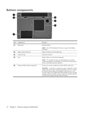
If you replace the module and then receive a warning message, remove the module to cool internal components. NOTE: The HP 530 Notebook PC does not support Smart Battery technology. Enables ...airflow to restore computer functionality, and then contact technical support through Help and Support. 10 Chapter 2 External component identification Release the battery from the battery bay. CAUTION: To prevent an unresponsive system, replace the wireless module only with a wireless module authorized for the internal fan...
If you replace the module and then receive a warning message, remove the module to cool internal components. NOTE: The HP 530 Notebook PC does not support Smart Battery technology. Enables ...airflow to restore computer functionality, and then contact technical support through Help and Support. 10 Chapter 2 External component identification Release the battery from the battery bay. CAUTION: To prevent an unresponsive system, replace the wireless module only with a wireless module authorized for the internal fan...

HP 530 Notebook PC - Maintenance and Service Guide
Page 63
... up. Optical drive (see Base enclosure on page 39) d. Base enclosure (see Optical drive on page 52) Remove the fan assembly: 1. Fan assembly Description Fan assembly Spare part number 438528-001 Before removing the fan assembly, follow these steps: 1. Remove the battery (see Switch cover on page 32). 5. Remove the following components: a. Remove... AC outlet and then unplugging the AC adapter from the system board. 2. Memory/WLAN module compartment cover (see Keyboard on page 35) c. Disconnect the fan cable (1) from the computer. 4. Component replacement procedures 55
... up. Optical drive (see Base enclosure on page 39) d. Base enclosure (see Optical drive on page 52) Remove the fan assembly: 1. Fan assembly Description Fan assembly Spare part number 438528-001 Before removing the fan assembly, follow these steps: 1. Remove the battery (see Switch cover on page 32). 5. Remove the following components: a. Remove... AC outlet and then unplugging the AC adapter from the system board. 2. Memory/WLAN module compartment cover (see Keyboard on page 35) c. Disconnect the fan cable (1) from the computer. 4. Component replacement procedures 55

HP 530 Notebook PC - Maintenance and Service Guide
Page 64
3. The computer uses an electric fan for ventilation. These conditions are affected by a temperature sensor and is displaced through the ventilation grill located on the left side of the computer. Remove the fan assembly (3). Reverse this procedure to turn on automatically when high ...Exhaust air is designed to install the fan assembly. NOTE: To properly ventilate the computer, allow at least a 7.6-cm (3-inch) clearance on the left and right sides of the computer. 56 Chapter 4 Removal and replacement procedures The fan is controlled by high external temperatures, system...
3. The computer uses an electric fan for ventilation. These conditions are affected by a temperature sensor and is displaced through the ventilation grill located on the left side of the computer. Remove the fan assembly (3). Reverse this procedure to turn on automatically when high ...Exhaust air is designed to install the fan assembly. NOTE: To properly ventilate the computer, allow at least a 7.6-cm (3-inch) clearance on the left and right sides of the computer. 56 Chapter 4 Removal and replacement procedures The fan is controlled by high external temperatures, system...

HP 530 Notebook PC - Maintenance and Service Guide
Page 65
...page 55) Remove the heat sink: 1. Shut down through the operating system. 2. Remove the battery (see Base enclosure on page 39) d. Fan assembly (see Memory module on page 47) g. Disconnect all external devices connected to the left until the right side of the thermal paste located between... cord from the AC outlet and then unplugging the AC adapter from the processor. Memory/WLAN module compartment cover (see Fan assembly on page 32). 5. Component replacement procedures 57 Display assembly (see Switch cover on , and then shut it may be necessary to move the heat sink...
...page 55) Remove the heat sink: 1. Shut down through the operating system. 2. Remove the battery (see Base enclosure on page 39) d. Fan assembly (see Memory module on page 47) g. Disconnect all external devices connected to the left until the right side of the thermal paste located between... cord from the AC outlet and then unplugging the AC adapter from the processor. Memory/WLAN module compartment cover (see Fan assembly on page 32). 5. Component replacement procedures 57 Display assembly (see Switch cover on , and then shut it may be necessary to move the heat sink...

HP 530 Notebook PC - Maintenance and Service Guide
Page 67
...Optical drive on page 32). 5. Optical drive (see Battery on page 39) d. Base enclosure (see Switch cover on page 52) h. Component replacement procedures 59 Disconnect the power from the computer by first unplugging the power cord from the AC outlet and then unplugging the AC adapter from... the computer. 4. Switch cover (see Base enclosure on page 41) e. Fan assembly (see Memory module on page 55) i. Memory/WLAN module compartment cover (see Fan assembly on page 35) c. Display assembly (see Heat sink on page 47) g. Heat sink (see ...
...Optical drive on page 32). 5. Optical drive (see Battery on page 39) d. Base enclosure (see Switch cover on page 52) h. Component replacement procedures 59 Disconnect the power from the computer by first unplugging the power cord from the AC outlet and then unplugging the AC adapter from... the computer. 4. Switch cover (see Base enclosure on page 41) e. Fan assembly (see Memory module on page 55) i. Memory/WLAN module compartment cover (see Fan assembly on page 35) c. Display assembly (see Heat sink on page 47) g. Heat sink (see ...

HP 530 Notebook PC - Maintenance and Service Guide
Page 70
Hard drive (see Base enclosure on page 33) b. Base enclosure (see Hard drive on page 52) h. Fan assembly (see Display assembly on page 55) i. Display assembly (see Fan assembly on page 47) g. Disconnect all external devices connected to the computer. 3. Disconnect the power from the... components: a. Heat sink (see Heat sink on page 39) d. Keyboard (see PC Card assembly on page 32). 5. Switch cover (see Battery on page 65) 62 Chapter 4 Removal and replacement procedures System board Description For use only with computer models with Intel Core processors and ...
Hard drive (see Base enclosure on page 33) b. Base enclosure (see Hard drive on page 52) h. Fan assembly (see Display assembly on page 55) i. Display assembly (see Fan assembly on page 47) g. Disconnect all external devices connected to the computer. 3. Disconnect the power from the... components: a. Heat sink (see Heat sink on page 39) d. Keyboard (see PC Card assembly on page 32). 5. Switch cover (see Battery on page 65) 62 Chapter 4 Removal and replacement procedures System board Description For use only with computer models with Intel Core processors and ...

HP 530 Notebook PC - Maintenance and Service Guide
Page 73
... board (see Battery on page 62) Remove the PC Card assembly: 1. Remove the battery (see System ...Fan assembly (see Memory module on page 55) i. PC Card assembly Description PC Card assembly PC Card slot bezel Spare part number 438551-001 438527-001 Before removing the PC... Card assembly, follow these steps: 1. Memory/WLAN module compartment cover (see Fan...system. 2. Position the system board with the PC Card eject button toward you are unsure whether...
... board (see Battery on page 62) Remove the PC Card assembly: 1. Remove the battery (see System ...Fan assembly (see Memory module on page 55) i. PC Card assembly Description PC Card assembly PC Card slot bezel Spare part number 438551-001 438527-001 Before removing the PC... Card assembly, follow these steps: 1. Memory/WLAN module compartment cover (see Fan...system. 2. Position the system board with the PC Card eject button toward you are unsure whether...

HP 530 Notebook PC - Maintenance and Service Guide
Page 75
... enclosure (see Memory module on page 52) h. Memory/WLAN module compartment cover (see Base enclosure on page 35) c. Display assembly (see Fan assembly on page 47) g. Component replacement procedures 67 Fan assembly (see Display assembly on page 55) i. Disconnect the power from the computer by first unplugging the power cord from the AC...
... enclosure (see Memory module on page 52) h. Memory/WLAN module compartment cover (see Base enclosure on page 35) c. Display assembly (see Fan assembly on page 47) g. Component replacement procedures 67 Fan assembly (see Display assembly on page 55) i. Disconnect the power from the computer by first unplugging the power cord from the AC...

HP 530 Notebook PC - Maintenance and Service Guide
Page 136
...21, 41 system backup 103, 109 system board removal 62 spare part numbers 15, 22, 62 System Configuration menu 73 system DMA 81 system fan 73 system information 71 system memory map 85 system recovery points 104, 110 removal 51 spare part number 16, 21, 51 wireless button 6... wireless light 6 wireless, product description 3 WLAN module removal 37 spare part numbers 14, 20, 37 workstation guidelines 28 T thermal material, replacement 58 tools required 25 top components 6 top cover, spare part number 13, 21 TouchPad 8 TouchPad cable removal 67 spare part number 13, 21, 67 ...
...21, 41 system backup 103, 109 system board removal 62 spare part numbers 15, 22, 62 System Configuration menu 73 system DMA 81 system fan 73 system information 71 system memory map 85 system recovery points 104, 110 removal 51 spare part number 16, 21, 51 wireless button 6... wireless light 6 wireless, product description 3 WLAN module removal 37 spare part numbers 14, 20, 37 workstation guidelines 28 T thermal material, replacement 58 tools required 25 top components 6 top cover, spare part number 13, 21 TouchPad 8 TouchPad cable removal 67 spare part number 13, 21, 67 ...


