HP PCL/PJL reference - Printer Job Language Technical Reference Addendum
Page 149
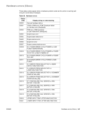
...or part malfunction [Designjet]) Engine fuser error 50004 50005 50006 50007 50008 50009 Engine beam detect error Engine scanner error Engine fan error Engine communications error 50.1 FUSER ERROR CYCLE POWER or LOW FUSER TEMPERATURE 50.2 ... 51.2 ERROR PRESS SELECT KEY or LASER MALFUNCTION 50014 50015 50016 50017 50018 50019 50020 50021 52.1 ERROR PRESS SELECT KEY or SCANNER STARTUP FAILURE 52.2 ERROR PRESS SELECT KEY or SCANNER ROTATION FAILURE 57.1 FAN FAILURE CALL ...) These status codes appear when a hardware problem exists but the printer is working well enough to send status messages.
...or part malfunction [Designjet]) Engine fuser error 50004 50005 50006 50007 50008 50009 Engine beam detect error Engine scanner error Engine fan error Engine communications error 50.1 FUSER ERROR CYCLE POWER or LOW FUSER TEMPERATURE 50.2 ... 51.2 ERROR PRESS SELECT KEY or LASER MALFUNCTION 50014 50015 50016 50017 50018 50019 50020 50021 52.1 ERROR PRESS SELECT KEY or SCANNER STARTUP FAILURE 52.2 ERROR PRESS SELECT KEY or SCANNER ROTATION FAILURE 57.1 FAN FAILURE CALL ...) These status codes appear when a hardware problem exists but the printer is working well enough to send status messages.
HP PCL/PJL reference - Printer Job Language Technical Reference Manual
Page 324
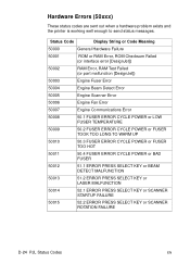
... 50002 RAM Error, RAM Test Failed (or part malfunction [DesignJet]) 50003 Engine Fuser Error 50004 Engine Beam Detect Error 50005 Engine Scanner Error 50006 Engine Fan Error 50007 Engine Communications Error 50008 50.1 FUSER ERROR CYCLE POWER or LOW FUSER TEMPERATURE 50009 50.2 FUSER ... SELECT KEY or BEAM DETECT MALFUNCTION 50013 51.2 ERROR PRESS SELECT KEY or LASER MALFUNCTION 50014 52.1 ERROR PRESS SELECT KEY or SCANNER STARTUP FAILURE 50015 52.2 ERROR PRESS SELECT KEY or SCANNER ROTATION FAILURE D-24 PJL Status Codes EN Hardware Errors (50xxx) These status codes...
... 50002 RAM Error, RAM Test Failed (or part malfunction [DesignJet]) 50003 Engine Fuser Error 50004 Engine Beam Detect Error 50005 Engine Scanner Error 50006 Engine Fan Error 50007 Engine Communications Error 50008 50.1 FUSER ERROR CYCLE POWER or LOW FUSER TEMPERATURE 50009 50.2 FUSER ... SELECT KEY or BEAM DETECT MALFUNCTION 50013 51.2 ERROR PRESS SELECT KEY or LASER MALFUNCTION 50014 52.1 ERROR PRESS SELECT KEY or SCANNER STARTUP FAILURE 50015 52.2 ERROR PRESS SELECT KEY or SCANNER ROTATION FAILURE D-24 PJL Status Codes EN Hardware Errors (50xxx) These status codes...
HP Color LaserJet 3500 and 3700 Series Printers - User Guide
Page 114
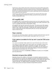
... 2400 dpi color laser-class quality with HP's multilevel printing process, result in a dot. Color options (available for the hp color LaserJet 3700 series printer) Color options automatically enable optimal color output for this printer. Using color The HP Color LaserJet 3500 series printer and the HP Color LaserJet 3700 series printer offer great color printing as soon as a common color language for the general office user. Also, the HP Color LaserJet 3700 series printer provides sophisticated...
... 2400 dpi color laser-class quality with HP's multilevel printing process, result in a dot. Color options (available for the hp color LaserJet 3700 series printer) Color options automatically enable optimal color output for this printer. Using color The HP Color LaserJet 3500 series printer and the HP Color LaserJet 3700 series printer offer great color printing as soon as a common color language for the general office user. Also, the HP Color LaserJet 3700 series printer provides sophisticated...
Service Manual
Page 9
...supplies ...94 Supplies life ...94 Approximate replacement intervals for supplies for the HP Color LaserJet 3500 series printer ...94 Approximate replacement intervals for supplies for the HP Color LaserJet 3550/3700 series printer 94 Locating supplies and parts ...96 Replacing supply items ...97 Replacing the ...119 DC controller PCB ...119 Low-voltage power supply circuit 126 Low-voltage power supply circuit 131 Laser/scanner system ...139 Laser control ...140 Scanner motor control ...144 Image formation system ...146 Print process ...147 Developing section ...156 Cartridge cleaning control...
...supplies ...94 Supplies life ...94 Approximate replacement intervals for supplies for the HP Color LaserJet 3500 series printer ...94 Approximate replacement intervals for supplies for the HP Color LaserJet 3550/3700 series printer 94 Locating supplies and parts ...96 Replacing supply items ...97 Replacing the ...119 DC controller PCB ...119 Low-voltage power supply circuit 126 Low-voltage power supply circuit 131 Laser/scanner system ...139 Laser control ...140 Scanner motor control ...144 Image formation system ...146 Print process ...147 Developing section ...156 Cartridge cleaning control...
Service Manual
Page 12
... HP Color LaserJet 3700 series printer 384 Standard red-green-blue (sRGB 384 Printing in four-colors [CMYK (available for the HP Color LaserJet 3700 series printer) ...385 CMYK ink set emulation (PostScript only 385 Managing color ...386 Print in Grayscale ...386 Automatic or manual color adjustment 386 Manual color options ...386 Matching colors ...388 Swatch book color matching (HP Color LaserJet 3700 series printer only 388 Adjusting color...
... HP Color LaserJet 3700 series printer 384 Standard red-green-blue (sRGB 384 Printing in four-colors [CMYK (available for the HP Color LaserJet 3700 series printer) ...385 CMYK ink set emulation (PostScript only 385 Managing color ...386 Print in Grayscale ...386 Automatic or manual color adjustment 386 Manual color options ...386 Matching colors ...388 Swatch book color matching (HP Color LaserJet 3700 series printer only 388 Adjusting color...
Service Manual
Page 21
...217 Transfer unit removal 219 Transfer unit installation 219 Print cartridge removal 220 Fuser removal 221 Face-down delivery assembly removal 222 Laser/scanner assembly removal 223 Image drive assembly removal 224 Developing engaging drive assembly removal 225 Pick-up/feed assembly removal (1 of 13...pad removal 238 Secondary transfer charging roller removal 239 Feed guide unit removal (1 of 2 240 Feed guide removal (2 of 2 241 Feed guide/printer drive shaft connection 241 Feed guide unit tab locations 241 Right swing guide removal (1 of 4 242 Right swing guide removal (2 of 4 ...
...217 Transfer unit removal 219 Transfer unit installation 219 Print cartridge removal 220 Fuser removal 221 Face-down delivery assembly removal 222 Laser/scanner assembly removal 223 Image drive assembly removal 224 Developing engaging drive assembly removal 225 Pick-up/feed assembly removal (1 of 13...pad removal 238 Secondary transfer charging roller removal 239 Feed guide unit removal (1 of 2 240 Feed guide removal (2 of 2 241 Feed guide/printer drive shaft connection 241 Feed guide unit tab locations 241 Right swing guide removal (1 of 4 242 Right swing guide removal (2 of 4 ...
Service Manual
Page 137
... system ...119 DC controller PCB ...119 Low-voltage power supply circuit 126 Low-voltage power supply circuit 131 Laser/scanner system ...139 Laser control ...140 Scanner motor control ...144 Image formation system ...146 Print process ...147 Developing section ...156 Cartridge cleaning control 163 ... 172 Secondary transfer roller engaging/disengaging detection 173 Color misregistration control 174 Image stabilization control 177 Pickup/feed system ...182 Pickup/feed unit ...184 Fuser/delivery unit ...189 Duplexing feed unit (HP 3700 printer only 192 Jam detection ...195 Paper feeder ......
... system ...119 DC controller PCB ...119 Low-voltage power supply circuit 126 Low-voltage power supply circuit 131 Laser/scanner system ...139 Laser control ...140 Scanner motor control ...144 Image formation system ...146 Print process ...147 Developing section ...156 Cartridge cleaning control 163 ... 172 Secondary transfer roller engaging/disengaging detection 173 Color misregistration control 174 Image stabilization control 177 Pickup/feed system ...182 Pickup/feed unit ...184 Fuser/delivery unit ...189 Duplexing feed unit (HP 3700 printer only 192 Jam detection ...195 Paper feeder ......
Service Manual
Page 138
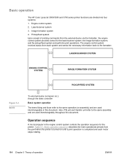
...HP Color LaserJet 3500/3550 and 3700 series printer functions are used interchangeably throughout this document. Laser/scanner system 3. Figure 5-1. Table 5-1. Engine control system 2. The engine control system receives status from each motor stops rotating. 114 Chapter 5 Theory of printing commands from the point when the printer...to the same assembly and are used interchangeably in the engine control system controls the operation sequence for the laser/scanner system, the image formation system, and the pickup/feed system and performs print operations. Basic operation sequence ...
...HP Color LaserJet 3500/3550 and 3700 series printer functions are used interchangeably throughout this document. Laser/scanner system 3. Figure 5-1. Table 5-1. Engine control system 2. The engine control system receives status from each motor stops rotating. 114 Chapter 5 Theory of printing commands from the point when the printer...to the same assembly and are used interchangeably in the engine control system controls the operation sequence for the laser/scanner system, the image formation system, and the pickup/feed system and performs print operations. Basic operation sequence ...
Service Manual
Page 143
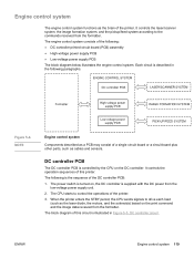
...functions as the brain of a single circuit board or a circuit board plus other parts, such as cables and sensors. It controls the laser/scanner system, the image formation system, and the pickup/feed system according to the commands received from the low-voltage power supply unit. 2. NOTE...PCB The DC controller PCB is illustrated in the following paragraphs. ENWW Engine control system 119 It controls the operation sequences of this printer. The block diagram of this circuit is controlled by the CPU on the print command and the image data received from the ...
...functions as the brain of a single circuit board or a circuit board plus other parts, such as cables and sensors. It controls the laser/scanner system, the image formation system, and the pickup/feed system according to the commands received from the low-voltage power supply unit. 2. NOTE...PCB The DC controller PCB is illustrated in the following paragraphs. ENWW Engine control system 119 It controls the operation sequences of this printer. The block diagram of this circuit is controlled by the CPU on the print command and the image data received from the ...
Service Manual
Page 145
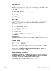
Laser/scanner 2. Communication with failure detector are listed in the following operations of the printer according to the commands from the EEP-ROM 7. High-voltage power supply circuit 4. Each motor's drive 5. EEP-ROM (IC1010) EEP-...(See Motors, solenoids, and clutches, below for details.) Motors, solenoids, and clutches This printer has seven motors, four solenoids (three for the HP Color LaserJet 3500/3550 series printer), and three clutches for paper feed and image formation. Printer engine sequence 2. Writing and reading data to and from the CPU: 1. The specifications of...
Laser/scanner 2. Communication with failure detector are listed in the following operations of the printer according to the commands from the EEP-ROM 7. High-voltage power supply circuit 4. Each motor's drive 5. EEP-ROM (IC1010) EEP-...(See Motors, solenoids, and clutches, below for details.) Motors, solenoids, and clutches This printer has seven motors, four solenoids (three for the HP Color LaserJet 3500/3550 series printer), and three clutches for paper feed and image formation. Printer engine sequence 2. Writing and reading data to and from the CPU: 1. The specifications of...
Service Manual
Page 159
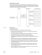
...) and sends the VERTICAL SYNCHRONOUS signal (/TOP) to monitor the printer status continuously. The DC controller controls each color's photosensitive drums. 7. It sends the VIDEO signal via the video interface when the printer is exchanged as follows during print: 1. The formatter sends the ... signal. 6. This forms a electrostatic latent image on each color's laser driver circuits and turns on /off the laser according to the VDO11~41 signals. ENWW Engine control system 135 The DC controller that drives the scanner motor sends the HORIZONTAL SYNCHRONOUS signals (/BD1, /BD2, /...
...) and sends the VERTICAL SYNCHRONOUS signal (/TOP) to monitor the printer status continuously. The DC controller controls each color's photosensitive drums. 7. It sends the VIDEO signal via the video interface when the printer is exchanged as follows during print: 1. The formatter sends the ... signal. 6. This forms a electrostatic latent image on each color's laser driver circuits and turns on /off the laser according to the VDO11~41 signals. ENWW Engine control system 135 The DC controller that drives the scanner motor sends the HORIZONTAL SYNCHRONOUS signals (/BD1, /BD2, /...
Service Manual
Page 164
NOTE NOTE NOTE NOTE 1. This printer has two scanner motors and generates two /BDI signals. This printer scans two lines with one scanner mirror. The scanning direction depends on the color. (Y and C: left to right, M and K: right to left) Laser control The laser control instructs the laser driver to turn on/off the four-face mirror passes through the...
NOTE NOTE NOTE NOTE 1. This printer has two scanner motors and generates two /BDI signals. This printer scans two lines with one scanner mirror. The scanning direction depends on the color. (Y and C: left to right, M and K: right to left) Laser control The laser control instructs the laser driver to turn on/off the four-face mirror passes through the...
Service Manual
Page 167
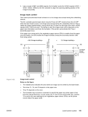
... ENWW Laser/scanner system 143 Image mask control This control prevents laser beam emission in a non-image area except during the unblanking interval. The timing to force the LD OFF while the laser beam scans a non-image area except during the unblanking interval. The DC controller puts the laser driver ...circuit to Force LD OFF mode to start the image mask control depends on the paper size information sent from the formatter. (This printer cannot detect the Tray 2 [cassette] paper size.) If the ...
... ENWW Laser/scanner system 143 Image mask control This control prevents laser beam emission in a non-image area except during the unblanking interval. The timing to force the LD OFF while the laser beam scans a non-image area except during the unblanking interval. The DC controller puts the laser driver ...circuit to Force LD OFF mode to start the image mask control depends on the paper size information sent from the formatter. (This printer cannot detect the Tray 2 [cassette] paper size.) If the ...
Service Manual
Page 169
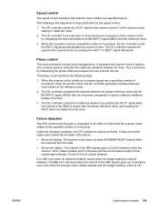
... ASIC to check that the scanner motor rotates at a constant speed to rotate the motor. 2. It stops the printer engine and notifies the formatter of the failure. ● Abnormal startup: The scanner motor does not enter SCANNER READY period within five seconds from...the /BD2I is off.) ENWW Laser/scanner system 145 Phase control This control prevents vertical color misregistration. It maintains the scanner motor's rotation at the specified number of revolutions. The DC controller forces the laser on the reference clock. 2. When the scanner motor rotates at a specified speed...
... ASIC to check that the scanner motor rotates at a constant speed to rotate the motor. 2. It stops the printer engine and notifies the formatter of the failure. ● Abnormal startup: The scanner motor does not enter SCANNER READY period within five seconds from...the /BD2I is off.) ENWW Laser/scanner system 145 Phase control This control prevents vertical color misregistration. It maintains the scanner motor's rotation at the specified number of revolutions. The DC controller forces the laser on the reference clock. 2. When the scanner motor rotates at a specified speed...
Service Manual
Page 170
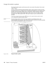
... are used interchangeably throughout this document. Figure 5-24. Image formation system 146 Chapter 5 Theory of units such as the nerve center of the printer, forms a toner image on paper according to the VIDEO signals (VDO, /VDO) upon receipt of a print command from the formatter. Image... formation system and Figure 5-25. The DC controller controls the laser/scanner unit and the high-voltage power supply circuit to the same operation (or assembly) and are used interchangeably in this document. The terms fixing...
... are used interchangeably throughout this document. Figure 5-24. Image formation system 146 Chapter 5 Theory of units such as the nerve center of the printer, forms a toner image on paper according to the VIDEO signals (VDO, /VDO) upon receipt of a print command from the formatter. Image... formation system and Figure 5-25. The DC controller controls the laser/scanner unit and the high-voltage power supply circuit to the same operation (or assembly) and are used interchangeably in this document. The terms fixing...
Service Manual
Page 228
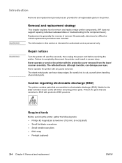
...handling sheet-metal parts. Be careful not to completely disconnect the printer could result in severe injury. The information in the printer. Never operate the printer with the protective cover removed from the laser/ scanner assembly. Protect the parts that are sensitive to ESD with ... is generally the reverse of removal. Removal and replacement strategy This chapter explains how to remove and replace major printer components. (HP does not support repairing individual subassemblies or troubleshooting to the component level.) Replacement is intended for the ESD reminder...
...handling sheet-metal parts. Be careful not to completely disconnect the printer could result in severe injury. The information in the printer. Never operate the printer with the protective cover removed from the laser/ scanner assembly. Protect the parts that are sensitive to ESD with ... is generally the reverse of removal. Removal and replacement strategy This chapter explains how to remove and replace major printer components. (HP does not support repairing individual subassemblies or troubleshooting to the component level.) Replacement is intended for the ESD reminder...
Service Manual
Page 229
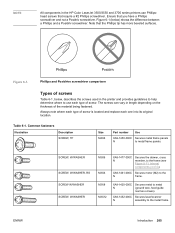
The screws can vary in the HP Color LaserJet 3500/3550 and 3700 series printers use each one into its original location. Common fasteners Illustration Description SCREW, TP Size M4X6 Part number Use XA9-1450-000C Secures metal frame panels N...Ensure that the Phillips tip has more beveled surfaces. Figure 6-1. Table 6-1. Note that you have a Phillips screwdriver and not a Posidriv screwdriver. XA9-1452-000C Secures laser/scanner N assembly to the N frame. Always note where each type of screw is located and replace each type of screw. XA9-1461-000C Secures motor (M2...
The screws can vary in the HP Color LaserJet 3500/3550 and 3700 series printers use each one into its original location. Common fasteners Illustration Description SCREW, TP Size M4X6 Part number Use XA9-1450-000C Secures metal frame panels N...Ensure that the Phillips tip has more beveled surfaces. Figure 6-1. Table 6-1. Note that you have a Phillips screwdriver and not a Posidriv screwdriver. XA9-1452-000C Secures laser/scanner N assembly to the N frame. Always note where each type of screw is located and replace each type of screw. XA9-1461-000C Secures motor (M2...
Service Manual
Page 241
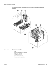
Main Assemblies The following procedures describe removal of the printer's major internal mechanical assemblies. Main internal assemblies 1 Fuser 2 Developing engaging drive assembly 3 Image drive assembly 4 Pick-up/feed assembly 5 Laser/scanner assembly 6 Transfer unit 7 Face-down delivery assembly ENWW Main Assemblies 217 Figure 6-16.
Main Assemblies The following procedures describe removal of the printer's major internal mechanical assemblies. Main internal assemblies 1 Fuser 2 Developing engaging drive assembly 3 Image drive assembly 4 Pick-up/feed assembly 5 Laser/scanner assembly 6 Transfer unit 7 Face-down delivery assembly ENWW Main Assemblies 217 Figure 6-16.
Service Manual
Page 247
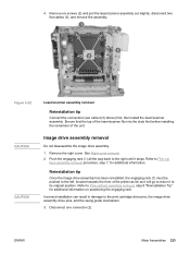
... out slightly, disconnect two flat cables (3), and remove the assembly. Ensure that the top of the laser/scanner fits into the slots first before installing the remainder of the printer as far as it will go to return it stops. See Right cover removal. 2. Push the engaging rack (1) all the way back ... the engaging rack. ENWW Main Assemblies 223 4. Image drive assembly removal Do not disassemble the image drive assembly. 1. Remove the right cover. CAUTION CAUTION Laser/scanner assembly removal Reinstallation tip Connect the connectors (see callout (3) above) first, then install the...
... out slightly, disconnect two flat cables (3), and remove the assembly. Ensure that the top of the laser/scanner fits into the slots first before installing the remainder of the printer as far as it will go to return it stops. See Right cover removal. 2. Push the engaging rack (1) all the way back ... the engaging rack. ENWW Main Assemblies 223 4. Image drive assembly removal Do not disassemble the image drive assembly. 1. Remove the right cover. CAUTION CAUTION Laser/scanner assembly removal Reinstallation tip Connect the connectors (see callout (3) above) first, then install the...

Service Manual
Page 327
... configuration 353 DC Controller (New) replacement configuration 353 DC Controller (previously installed in another printer) replacement configuration ........354 Media sensor (PS5) replacement configuration 354 Color Misregistration Sensor (PS12) replacement configuration 355 Laser/scanner Assembly replacement configuration 355 Fuser replacement configuration 355 Transfer unit (ITB assembly) replacement configuration 355 Paper path troubleshooting 356 Paper path...
... configuration 353 DC Controller (New) replacement configuration 353 DC Controller (previously installed in another printer) replacement configuration ........354 Media sensor (PS5) replacement configuration 354 Color Misregistration Sensor (PS12) replacement configuration 355 Laser/scanner Assembly replacement configuration 355 Fuser replacement configuration 355 Transfer unit (ITB assembly) replacement configuration 355 Paper path troubleshooting 356 Paper path...


