
Service Manual
Page 6
...printer from the HP Toolbox 36 4 Operational theory Engine control system ...38 Basic sequence of operation 38 Power-on sequence ...39 Motors and fans ...39 Main motor failure detection 40 Fan motor failure detection 40 Image formation system ...41 Image formation process ...43 Latent image formation 44 Laser.../scanner system 45 Developing stage ...45 Print cartridge ...46 Transfer belt (ETB 47 Transfer stage ...48 Separation stage ...49 Fusing stage ...49 Pickup and feed ...
...printer from the HP Toolbox 36 4 Operational theory Engine control system ...38 Basic sequence of operation 38 Power-on sequence ...39 Motors and fans ...39 Main motor failure detection 40 Fan motor failure detection 40 Image formation system ...41 Image formation process ...43 Latent image formation 44 Laser.../scanner system 45 Developing stage ...45 Print cartridge ...46 Transfer belt (ETB 47 Transfer stage ...48 Separation stage ...49 Fusing stage ...49 Pickup and feed ...

Service Manual
Page 13
... Figure 7-5 Figure 7-6 Figure 7-7 Figure 7-8 Figure 7-9 Figure 7-10 HP Color LaserJet 2600n printer...3 Front view (shown with optional Tray 3 6 Back and side view...7 Transfer belt (ETB) and print cartridges 7 Model and serial number information 8 Control ...panel layout...10 Control panel display...10 Envelope double side-seam construction 16 Printer dimensions ...22 Package contents ...24 Engine control system ...39 Image formation system ...42 Image formation process ...43 Latent image formation ...45 Laser...
... Figure 7-5 Figure 7-6 Figure 7-7 Figure 7-8 Figure 7-9 Figure 7-10 HP Color LaserJet 2600n printer...3 Front view (shown with optional Tray 3 6 Back and side view...7 Transfer belt (ETB) and print cartridges 7 Model and serial number information 8 Control ...panel layout...10 Control panel display...10 Envelope double side-seam construction 16 Printer dimensions ...22 Package contents ...24 Engine control system ...39 Image formation system ...42 Image formation process ...43 Latent image formation ...45 Laser...
Service Manual
Page 21
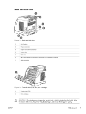
Walk around 7 Otherwise, the printer may be damaged, adversely affecting print quality. Back and side view Figure 1-3 Back and side view 1 On/off switch 2 Power connection 3 Engine test button access door 4 Access door 5 Dust cover 6 HP built-in internal print server for connecting to a 10/100Base-T network 7 USB connection Figure 1-4 Transfer belt (ETB) and print cartridges 1 Transfer belt (ETB) 2 Print cartridges ENWW CAUTION Do not place anything on the transfer belt , which is located on the inside of the front door.
Walk around 7 Otherwise, the printer may be damaged, adversely affecting print quality. Back and side view Figure 1-3 Back and side view 1 On/off switch 2 Power connection 3 Engine test button access door 4 Access door 5 Dust cover 6 HP built-in internal print server for connecting to a 10/100Base-T network 7 USB connection Figure 1-4 Transfer belt (ETB) and print cartridges 1 Transfer belt (ETB) 2 Print cartridges ENWW CAUTION Do not place anything on the transfer belt , which is located on the inside of the front door.
Service Manual
Page 41
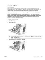
The control panel display also indicates the color that you to replace the cartridge. CAUTION Do not place anything on the transfer belt (ETB), which is not currently installed). The printer can continue to print using the current print ...printer uses four colors and has a different print cartridge for each color: black (K), cyan (C), magenta (M), and yellow (Y). ENWW Install input devices 27 Installing supplies Print cartridges When a print cartridge approaches the end of useful life, the control panel displays a message recommending that should be replaced (unless a genuine HP...
The control panel display also indicates the color that you to replace the cartridge. CAUTION Do not place anything on the transfer belt (ETB), which is not currently installed). The printer can continue to print using the current print ...printer uses four colors and has a different print cartridge for each color: black (K), cyan (C), magenta (M), and yellow (Y). ENWW Install input devices 27 Installing supplies Print cartridges When a print cartridge approaches the end of useful life, the control panel displays a message recommending that should be replaced (unless a genuine HP...

Service Manual
Page 54
... the following condition. Failure detection Yes No No Yes Main motor failure detection The CPU determines the main motor failure, stops the printer, and notifies the formatter of error status, when it has become the specified interval after 1000 ms of the main motor drive start...interval. The specifications of rotation CW CW/CCW CW - Table 4-2 Motor specifications Name Motor Purpose Type Main motor (M1) Drive ETB belt, photosensitive drum and developing cylinder DC motor Fuser/delivery motor (M2) Drive fuser pressure roller, delivery roller and automatic release of fuser ...
... the following condition. Failure detection Yes No No Yes Main motor failure detection The CPU determines the main motor failure, stops the printer, and notifies the formatter of error status, when it has become the specified interval after 1000 ms of the main motor drive start...interval. The specifications of rotation CW CW/CCW CW - Table 4-2 Motor specifications Name Motor Purpose Type Main motor (M1) Drive ETB belt, photosensitive drum and developing cylinder DC motor Fuser/delivery motor (M2) Drive fuser pressure roller, delivery roller and automatic release of fuser ...
Service Manual
Page 61
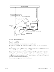
... As the main motor rotates the ETB feed roller, the ETB feed roller rotates the ETB belt. The pattern image for color misregistration corrective control and the image stabilization control. The following is conveyed in the color misregistration/density sensor unit. During printing, the picked up paper is the diagrammatic sketch of the...
... As the main motor rotates the ETB feed roller, the ETB feed roller rotates the ETB belt. The pattern image for color misregistration corrective control and the image stabilization control. The following is conveyed in the color misregistration/density sensor unit. During printing, the picked up paper is the diagrammatic sketch of the...
Service Manual
Page 78
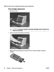
Place the used print cartridge from the printer. 3 Remove the new print cartridge from the bag. Removal and replacement procedures Print cartridge replacement 1 Open the front door. CAUTION Do not place anything on the transfer belt (ETB), which is located on the inside of the front door. 2 Remove the used print cartridge in the bag for recycling. 64 Chapter 5 Removal and replacement ENWW
Place the used print cartridge from the printer. 3 Remove the new print cartridge from the bag. Removal and replacement procedures Print cartridge replacement 1 Open the front door. CAUTION Do not place anything on the transfer belt (ETB), which is located on the inside of the front door. 2 Remove the used print cartridge in the bag for recycling. 64 Chapter 5 Removal and replacement ENWW

Service Manual
Page 116
...all cases, grasp the jammed paper by using the instructions on the inside of the jam is located on the following pages. Otherwise, the printer may be damaged, adversely affecting print quality. 102 Chapter 6 Troubleshooting ENWW This problem should resolve itself after a jam. Loose toner might result... hands, wash them in loose toner on the page. If the location of the front door. Jams inside the printer Use the following procedures to clear jams from inside the printer. CAUTION Do not place anything on the transfer belt, which is not obvious, first look inside the...
...all cases, grasp the jammed paper by using the instructions on the inside of the jam is located on the following pages. Otherwise, the printer may be damaged, adversely affecting print quality. 102 Chapter 6 Troubleshooting ENWW This problem should resolve itself after a jam. Loose toner might result... hands, wash them in loose toner on the page. If the location of the front door. Jams inside the printer Use the following procedures to clear jams from inside the printer. CAUTION Do not place anything on the transfer belt, which is not obvious, first look inside the...

Service Manual
Page 182
Ref Description 33 SPRING, COMPRESSION 34 ELECT.TRANSPORT BELT ASS'Y 35 RING, E 36 SCREW, RS, M3X6 37 SCREW, RS, M3X8 38 SCREW, W/WASHER, M4X18 501 SCREW, TAPPING, TRUSS HEAD, M4X8 A01 GEAR, 29T A02 GEAR, 29T A03 SPRING, COMPRESSION Part number Qty * 1 RM1-1885-000CN 1 * 2 * 2 * 19 * 2 * 2 * 1 * 1 * 1 168 Chapter 7 Parts and diagrams ENWW
Ref Description 33 SPRING, COMPRESSION 34 ELECT.TRANSPORT BELT ASS'Y 35 RING, E 36 SCREW, RS, M3X6 37 SCREW, RS, M3X8 38 SCREW, W/WASHER, M4X18 501 SCREW, TAPPING, TRUSS HEAD, M4X8 A01 GEAR, 29T A02 GEAR, 29T A03 SPRING, COMPRESSION Part number Qty * 1 RM1-1885-000CN 1 * 2 * 2 * 19 * 2 * 2 * 1 * 1 * 1 168 Chapter 7 Parts and diagrams ENWW
Service Manual
Page 191
... FLANGE, CAM GEAR A04 COVER, DRUM A05 BUSHING A06 BUSHING A07 CAM, RELEASE A08 ROD, RELEASE, RIGHT A09 FAN A10 DUCT, FAN A11 PULLEY A12 BELT, TRANSMISSION A13 STOP, CAM GEAR A14 BUSHING A15 GUIDE, DRIVE CABLE A16 MOTOR, DC A17 SOLENOID A18 PLATE, DRIVE INSIDE A19 SIDE PLATE, DRIVE A20...
... FLANGE, CAM GEAR A04 COVER, DRUM A05 BUSHING A06 BUSHING A07 CAM, RELEASE A08 ROD, RELEASE, RIGHT A09 FAN A10 DUCT, FAN A11 PULLEY A12 BELT, TRANSMISSION A13 STOP, CAM GEAR A14 BUSHING A15 GUIDE, DRIVE CABLE A16 MOTOR, DC A17 SOLENOID A18 PLATE, DRIVE INSIDE A19 SIDE PLATE, DRIVE A20...

Service Manual
Page 224
... ARM, MD. ARM, REMNANT INDICATION ARM, REMNANT INDICATION BACK END LIMIT PLATE ASS'Y BACK END LIMIT PLATE ASS'Y BASE PLATE, FIXING BASE, MOTOR BASE, MOTOR BELT, TRANSMISSION BODY, CASSETTE BODY, CASSETTE BRACKET, CARD READER BRACKET, LEFT REAR BRACKET, RIGHT REAR BUSHING BUSHING BUSHING 210 Chapter 7 Parts and diagrams Part number * * * RC1..., RIGHT ARM, PLATE LOCK RELEASE, MD ARM, PLATE LOCK RELEASE, MD. PAPER SENSING, 2 ARM, FRONT DOOR, LEFT ARM, FRONT DOOR, RIGHT ARM, INTERLOCK SWITCH ARM, LASER SHUTTER ARM, MD.
... ARM, MD. ARM, REMNANT INDICATION ARM, REMNANT INDICATION BACK END LIMIT PLATE ASS'Y BACK END LIMIT PLATE ASS'Y BASE PLATE, FIXING BASE, MOTOR BASE, MOTOR BELT, TRANSMISSION BODY, CASSETTE BODY, CASSETTE BRACKET, CARD READER BRACKET, LEFT REAR BRACKET, RIGHT REAR BUSHING BUSHING BUSHING 210 Chapter 7 Parts and diagrams Part number * * * RC1..., RIGHT ARM, PLATE LOCK RELEASE, MD ARM, PLATE LOCK RELEASE, MD. PAPER SENSING, 2 ARM, FRONT DOOR, LEFT ARM, FRONT DOOR, RIGHT ARM, INTERLOCK SWITCH ARM, LASER SHUTTER ARM, MD.

Service Manual
Page 229
... COVER DC CONTROLLER PCB ASS'Y DC CONTROLLER PCB ASS'Y DOOR, FRONT DRIVE CABLE DUCT, FAN DUCT, FAN DUCT, FAN, LOWER DUCT, FAN, UPPER ELECT.TRANSPORT BELT ASS'Y EXTERNAL COVERS, PANELS, ETC. F.F.C. CONNECT PCB UNIT FAN FAN FEED ASS'Y FEEDER UNIT CABLE FEEDER UNIT JOINT CABLE FEEDER UNIT JOINT CABLE FILM GUIDE...
... COVER DC CONTROLLER PCB ASS'Y DC CONTROLLER PCB ASS'Y DOOR, FRONT DRIVE CABLE DUCT, FAN DUCT, FAN DUCT, FAN, LOWER DUCT, FAN, UPPER ELECT.TRANSPORT BELT ASS'Y EXTERNAL COVERS, PANELS, ETC. F.F.C. CONNECT PCB UNIT FAN FAN FEED ASS'Y FEEDER UNIT CABLE FEEDER UNIT JOINT CABLE FEEDER UNIT JOINT CABLE FILM GUIDE...
Service Manual
Page 251
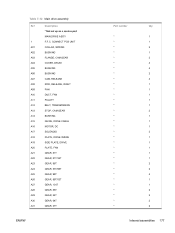
Table 7-23 Numerical parts list (continued) Part number Description * BELT, TRANSMISSION * STOP, CAM GEAR * BUSHING * GUIDE, DRIVE CABLE * MOTOR, DC * SOLENOID * PLATE, DRIVE INSIDE * SIDE PLATE, DRIVE * PLATE, FAN * GEAR, 81T * GEAR, 81T/32T * GEAR, ...
Table 7-23 Numerical parts list (continued) Part number Description * BELT, TRANSMISSION * STOP, CAM GEAR * BUSHING * GUIDE, DRIVE CABLE * MOTOR, DC * SOLENOID * PLATE, DRIVE INSIDE * SIDE PLATE, DRIVE * PLATE, FAN * GEAR, 81T * GEAR, 81T/32T * GEAR, ...

Service Manual
Page 264
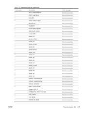
...-1922-000CN RM1-1923-000CN RM1-1945-000CN RM1-1945-000CN RM1-1975-000CN RM1-1975-000CN RM1-1983-000CN RM1-1983-000CN ELECT.TRANSPORT BELT ASS'Y CASSETTE CASSETTE SEPARATION ASS'Y SEPARATION ASS'Y FEED ASS'Y CASSETTE CASSETTE DC CONTROLLER PCB ASS'Y DC CONTROLLER PCB ASS'Y CONTROL PANEL ASSEMBLY CONTROL PANEL ASS...
...-1922-000CN RM1-1923-000CN RM1-1945-000CN RM1-1945-000CN RM1-1975-000CN RM1-1975-000CN RM1-1983-000CN RM1-1983-000CN ELECT.TRANSPORT BELT ASS'Y CASSETTE CASSETTE SEPARATION ASS'Y SEPARATION ASS'Y FEED ASS'Y CASSETTE CASSETTE DC CONTROLLER PCB ASS'Y DC CONTROLLER PCB ASS'Y CONTROL PANEL ASSEMBLY CONTROL PANEL ASS...


