
Owners Manual
Page 3
...-step instructions 8 Installation in Combination with Solar or Gas Heaters 10 Using an External Controller 11 Electrical Connections 12 Wiring Diagram 13 Service Analyzer Control 14 Operation 15 Caring for your Pool Heater 16 Initial Startup 17 Meaning of Display Codes 18 Troubleshooting ...19 Requesting Assistance or Service 21 Maintenance 22 Winterizing 22 Hayward® Heat Pump Pool Heater Limited Warranty 23 ...
...-step instructions 8 Installation in Combination with Solar or Gas Heaters 10 Using an External Controller 11 Electrical Connections 12 Wiring Diagram 13 Service Analyzer Control 14 Operation 15 Caring for your Pool Heater 16 Initial Startup 17 Meaning of Display Codes 18 Troubleshooting ...19 Requesting Assistance or Service 21 Maintenance 22 Winterizing 22 Hayward® Heat Pump Pool Heater Limited Warranty 23 ...
Owners Manual
Page 13
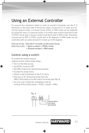
Next, access the P_S menu and select the desired mode. Using an External Controller To connect the electronic board in SPA mode can be adjusted by turning off the switch (open = POOL, closed = SPA.) Fig. 4 External switch Pool (open contact puts the board in POOL mode and a closed ) Owner's manual 11...board. Internal mode: Use the P_S mode on the main menu External mode: • Open contact = POOL mode • Closed contact = SPA mode Control using a switch To control the board using this menu. Therefore, a board set to OFF in POOL mode and to 80 degrees in order to the NO switch...
Next, access the P_S menu and select the desired mode. Using an External Controller To connect the electronic board in SPA mode can be adjusted by turning off the switch (open = POOL, closed = SPA.) Fig. 4 External switch Pool (open contact puts the board in POOL mode and a closed ) Owner's manual 11...board. Internal mode: Use the P_S mode on the main menu External mode: • Open contact = POOL mode • Closed contact = SPA mode Control using a switch To control the board using this menu. Therefore, a board set to OFF in POOL mode and to 80 degrees in order to the NO switch...

Owners Manual
Page 14
.... Fig. 5 L1 L2 Ground 12 Owner's manual The electrical diagram is located on the left or the right side of the control box as well as in the control box. To connect the electricity, you must unscrew the five screws of the front panel, then slide the electric cable through the... knock out located on the lid of the base, and then insert it in this manual. Electrical Connections WARNING The installation of the pool heater should be...
.... Fig. 5 L1 L2 Ground 12 Owner's manual The electrical diagram is located on the left or the right side of the control box as well as in the control box. To connect the electricity, you must unscrew the five screws of the front panel, then slide the electric cable through the... knock out located on the lid of the base, and then insert it in this manual. Electrical Connections WARNING The installation of the pool heater should be...

Owners Manual
Page 15
13 Owner's manual HPEC-003 Control Board Water sensor Defrost sensor High pressure switch Closed = OK Opened = high pressure Low pressure switch Closed = OK Opened = low pressure Flow switch Closed = flow ... COMPRESSOR FAN FAN Black Brown Brown FAN CAP CAP S COMPRESSOR R C Yellow Yellow HGD H/C 24 VAC PS Yellow 24 Vac Red Brown Remote switch Pool (opened) Spa (closed) Black Blue 24 Vac transformer Orange (240 Vac) or Red (208 Vac) 24 Vac compressor contactor L1 L2 Ground 208 / 230 Vac, 60 Hz...
13 Owner's manual HPEC-003 Control Board Water sensor Defrost sensor High pressure switch Closed = OK Opened = high pressure Low pressure switch Closed = OK Opened = low pressure Flow switch Closed = flow ... COMPRESSOR FAN FAN Black Brown Brown FAN CAP CAP S COMPRESSOR R C Yellow Yellow HGD H/C 24 VAC PS Yellow 24 Vac Red Brown Remote switch Pool (opened) Spa (closed) Black Blue 24 Vac transformer Orange (240 Vac) or Red (208 Vac) 24 Vac compressor contactor L1 L2 Ground 208 / 230 Vac, 60 Hz...

Owners Manual
Page 16
Celsius or Fahrenheit mode Temperature and parameter display Access to parameters Heating mode Compressor ( ) or fan ( ) running Heating mode To raise the desired temperature or to change parameters To lower the desired temperature or to display the temperature in Fahrenheit degrees. Service Analyzer Control The control panel is factory set to change parameters 14 Owner's manual
Celsius or Fahrenheit mode Temperature and parameter display Access to parameters Heating mode Compressor ( ) or fan ( ) running Heating mode To raise the desired temperature or to change parameters To lower the desired temperature or to display the temperature in Fahrenheit degrees. Service Analyzer Control The control panel is factory set to change parameters 14 Owner's manual

Owners Manual
Page 19
... holes at the base of the unit. Also make sure that the water circulates freely and that the breaker is important to see "Service Analyzer Control," p. 13) should be lit. At initial startup, it is normal for the first time, it is in the ON position. Owner's manual 17 The compressor... 4-minute delay. It is also normal to verify that the pool pump is just condensation. This is activited. Initial Startup ? IMPORTANT Before starting the pool heater for the unit to set the water temperature you will need to run 24 hours a day.
... holes at the base of the unit. Also make sure that the water circulates freely and that the breaker is important to see "Service Analyzer Control," p. 13) should be lit. At initial startup, it is normal for the first time, it is in the ON position. Owner's manual 17 The compressor... 4-minute delay. It is also normal to verify that the pool pump is just condensation. This is activited. Initial Startup ? IMPORTANT Before starting the pool heater for the unit to set the water temperature you will need to run 24 hours a day.

Owners Manual
Page 20
...disconnected. If it is short circuited or may be defective. Shortage of refrigerant gas in the unit or faulty low pressure control. The filter is normal operation when outside temperatures are cold. 18 Owner's manual This is dirty. - The pool pump...heater. Po Water temperature probe connected to pool pump. - FLo Possible causes: - The filter is broken. Water pressure switch must be adjusted or it is in defrosting cycle (the fan works but the compressor is used. dPo Suction temperature probe connected to the unit or faulty high pressure control...
...disconnected. If it is short circuited or may be defective. Shortage of refrigerant gas in the unit or faulty low pressure control. The filter is normal operation when outside temperatures are cold. 18 Owner's manual This is dirty. - The pool pump...heater. Po Water temperature probe connected to pool pump. - FLo Possible causes: - The filter is broken. Water pressure switch must be adjusted or it is in defrosting cycle (the fan works but the compressor is used. dPo Suction temperature probe connected to the unit or faulty high pressure control...

Owners Manual
Page 21
Heat pump control set point above 60°F (15°C). Desired water temperature is dirty, restricting the water flow. Reset main breaker and restart heat pump. Filter is reached. The compressor will automatically restart when the water temperature goes below the set point. Unit will automatically start . The heater is displaying "flo"... 19 Pool pump is not. The fan is running, but the compressor is not running . The heat pump is not running . Troubleshooting The pool heater is in protection mode. Main breaker is on . Turn the pool pump on defrost cycle.
Heat pump control set point above 60°F (15°C). Desired water temperature is dirty, restricting the water flow. Reset main breaker and restart heat pump. Filter is reached. The compressor will automatically restart when the water temperature goes below the set point. Unit will automatically start . The heater is displaying "flo"... 19 Pool pump is not. The fan is running, but the compressor is not running . The heat pump is not running . Troubleshooting The pool heater is in protection mode. Main breaker is on . Turn the pool pump on defrost cycle.

