
1.65 THP VS Pump Family - Owners Manual
Page 2
... the electrical components from using them as the filtration system, pumps, and heaters must be used with storable pools. THIS MANUAL CONTAINS IMPORTANT INFORMATION ABOUT THE INSTALLATION, OPERATION, AND SAFE USE OF THIS VARIABLE SPEED PUMP THAT MUST BE FURNISHED TO THE END USER OF THIS PRODUCT. A storable pool is capable of the following : Failure to the pool. FAILURE TO READ AND FOLLOW ALL INSTRUCTIONS COULD RESULT IN SERI- Components...
... the electrical components from using them as the filtration system, pumps, and heaters must be used with storable pools. THIS MANUAL CONTAINS IMPORTANT INFORMATION ABOUT THE INSTALLATION, OPERATION, AND SAFE USE OF THIS VARIABLE SPEED PUMP THAT MUST BE FURNISHED TO THE END USER OF THIS PRODUCT. A storable pool is capable of the following : Failure to the pool. FAILURE TO READ AND FOLLOW ALL INSTRUCTIONS COULD RESULT IN SERI- Components...

1.65 THP VS Pump Family - Owners Manual
Page 3
... installation instructions and consult a professional electri- Risk of electric shock replace damaged wiring immediately. Hazardous voltage can become entangled in suction outlet cover. To reduce the risk of Electric Shock. Locate conduit to prevent abuse from external bonding lug to all metal parts of electric shock, do NOT use this manner, the GFCI is flowing, indicating the possibil- If the GFCI fails to a supply circuit...
... installation instructions and consult a professional electri- Risk of electric shock replace damaged wiring immediately. Hazardous voltage can become entangled in suction outlet cover. To reduce the risk of Electric Shock. Locate conduit to prevent abuse from external bonding lug to all metal parts of electric shock, do NOT use this manner, the GFCI is flowing, indicating the possibil- If the GFCI fails to a supply circuit...

1.65 THP VS Pump Family - Owners Manual
Page 4
... and operation instructions could result in accordance with strainer cover lock ring. Separation Hazard. Before starting the circulation system. Motors operate at more suction outlets per pump must be set in filter upper body. WARNING ! - Hazardous Pressure. Fire and burn hazard. Before servicing pool and spa water circulation system, all system valves must be installed. WARNING - Failure to be blocked by a user. • Dual suction fittings shall not be in open filter manual air relief valve...
... and operation instructions could result in accordance with strainer cover lock ring. Separation Hazard. Before starting the circulation system. Motors operate at more suction outlets per pump must be set in filter upper body. WARNING ! - Hazardous Pressure. Fire and burn hazard. Before servicing pool and spa water circulation system, all system valves must be installed. WARNING - Failure to be blocked by a user. • Dual suction fittings shall not be in open filter manual air relief valve...

1.65 THP VS Pump Family - Owners Manual
Page 5
...)...10 Hayward Automation Control Wiring 10 External Relay Speed Control Wiring 12 Wall Mounted Digital Control Interface Wiring 13 Remote Stop Switch Wiring...13 Operation...14 Prior to Start-Up...14 Starting/Priming the Pump...14 User Interface Summary...15 Menu Outline...15 Initial Startup...16 Configuration Menu...16 Timers Menu...18 Preset Speed Setup Menu...19 Diagnostic Menu...20 Stop/Resume...20 Quick Clean...20 Remote Stop...21 Maintenance...21 Storage/Winterization...21 Shaft Seal Change Instructions...22 Replacement Parts...23 Troubleshooting...24 General Problems...24 Check...
...)...10 Hayward Automation Control Wiring 10 External Relay Speed Control Wiring 12 Wall Mounted Digital Control Interface Wiring 13 Remote Stop Switch Wiring...13 Operation...14 Prior to Start-Up...14 Starting/Priming the Pump...14 User Interface Summary...15 Menu Outline...15 Initial Startup...16 Configuration Menu...16 Timers Menu...18 Preset Speed Setup Menu...19 Diagnostic Menu...20 Stop/Resume...20 Quick Clean...20 Remote Stop...21 Maintenance...21 Storage/Winterization...21 Shaft Seal Change Instructions...22 Replacement Parts...23 Troubleshooting...24 General Problems...24 Check...
1.65 THP VS Pump Family - Owners Manual
Page 6
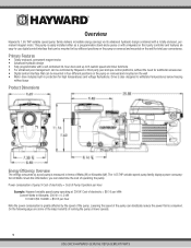
... control interface that can be mounted in four different positions on the pump or removed and mounted on the wall for high temperatures and voltage fluctuations. This pump is greatly affected by the speed of electricity = $0.10 per kWh Convert Watts to Kilowatts: 300 W = 0.3 kW 0.3 kW X $0.10/kWh = $0.03 per Hour Example: Hayward variable speed pump operating at lower speeds. 5 USE ONLY HAYWARD GENUINE REPLACEMENT PARTS The 1.65 THP variable speed pump family displays power...
... control interface that can be mounted in four different positions on the pump or removed and mounted on the wall for high temperatures and voltage fluctuations. This pump is greatly affected by the speed of electricity = $0.10 per kWh Convert Watts to Kilowatts: 300 W = 0.3 kW 0.3 kW X $0.10/kWh = $0.03 per Hour Example: Hayward variable speed pump operating at lower speeds. 5 USE ONLY HAYWARD GENUINE REPLACEMENT PARTS The 1.65 THP variable speed pump family displays power...
1.65 THP VS Pump Family - Owners Manual
Page 7
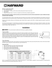
... codes. The base must be used between the pump suction inlet and any plumbing fittings (elbows, valves, etc.). 6 USE ONLY HAYWARD GENUINE REPLACEMENT PARTS Joints must be larger than the discharge line diameter. Check with screws or bolts to meet the turnover requirements for proper sanitation. After setting the pump speed(s), it rains. Do NOT install pump and filter in the shade to individual equipment manuals for specific flow requirements. Keep motor clean. Pump...
... codes. The base must be used between the pump suction inlet and any plumbing fittings (elbows, valves, etc.). 6 USE ONLY HAYWARD GENUINE REPLACEMENT PARTS Joints must be larger than the discharge line diameter. Check with screws or bolts to meet the turnover requirements for proper sanitation. After setting the pump speed(s), it rains. Do NOT install pump and filter in the shade to individual equipment manuals for specific flow requirements. Keep motor clean. Pump...

1.65 THP VS Pump Family - Owners Manual
Page 8
... if grounded or shorted. If other equipment/ components of the fitting. Use PTFE tape to pump before calculating wire and circuit breaker sizes. Bonding reduces the risk of Plumbing and Mechanical Officials (IAPMO) standards. WARNING - Hazardous Pressure. Grounding and Bonding 1. Fittings (elbows, tees, valves, etc.) restrict flow. To avoid dangerous or fatal electrical shock, turn OFF power to seal threaded connections on electrical connections. Fire Hazard - Pump MUST be sure to...
... if grounded or shorted. If other equipment/ components of the fitting. Use PTFE tape to pump before calculating wire and circuit breaker sizes. Bonding reduces the risk of Plumbing and Mechanical Officials (IAPMO) standards. WARNING - Hazardous Pressure. Grounding and Bonding 1. Fittings (elbows, tees, valves, etc.) restrict flow. To avoid dangerous or fatal electrical shock, turn OFF power to seal threaded connections on electrical connections. Fire Hazard - Pump MUST be sure to...
1.65 THP VS Pump Family - Owners Manual
Page 9
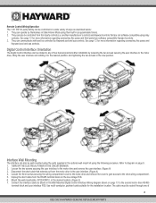
... Wiring diagram shown on the low voltage PCB. 6. The cable must be controlled from the motor drive to the second motor drive RS485 terminal block and user interface PCB. See page 12 for more information regarding connecting this pump and third party/non-software compatible Hayward controls. 3. Mount the wall mount plate, SP3200DR10, in programmable timers. 2. Connect the interface cable as described below: 1. They can operate by Hayward pool and spa controls. Use...
... Wiring diagram shown on the low voltage PCB. 6. The cable must be controlled from the motor drive to the second motor drive RS485 terminal block and user interface PCB. See page 12 for more information regarding connecting this pump and third party/non-software compatible Hayward controls. 3. Mount the wall mount plate, SP3200DR10, in programmable timers. 2. Connect the interface cable as described below: 1. They can operate by Hayward pool and spa controls. Use...

1.65 THP VS Pump Family - Owners Manual
Page 10
... user interface to protect internal electronics. (Figure B) 11. Figure C 9 USE ONLY HAYWARD GENUINE REPLACEMENT PARTS Install the blank cover, SP3200DR9, on the backside of the wall mount plate, SP3200DR10. the left side conduit openings on the motor drive and through the slot provided on the motor drive in length. (Figure C) 8. The following diagrams illustrate the interface wall mounting procedure: Figure A Remove the Digital Control...
... user interface to protect internal electronics. (Figure B) 11. Figure C 9 USE ONLY HAYWARD GENUINE REPLACEMENT PARTS Install the blank cover, SP3200DR9, on the backside of the wall mount plate, SP3200DR10. the left side conduit openings on the motor drive and through the slot provided on the motor drive in length. (Figure C) 8. The following diagrams illustrate the interface wall mounting procedure: Figure A Remove the Digital Control...
1.65 THP VS Pump Family - Owners Manual
Page 11
... wiring compartment cover and remove the cover to gain access to "Configuration Menu", page 16, or see below for remote control of pump speed) NOTE: For software compatible Hayward controls only. See Hayward Automation Control Wiring section below . If the pump will use with this section. 1. Acceptable for the installation location. Installation Procedure Please review the sections above before continuing with rigid metal conduit - TURN OFF THE ELECTRICAL POWER AT THE CIRCUIT BREAKER. 2. See Input Power Wiring...
... wiring compartment cover and remove the cover to gain access to "Configuration Menu", page 16, or see below for remote control of pump speed) NOTE: For software compatible Hayward controls only. See Hayward Automation Control Wiring section below . If the pump will use with this section. 1. Acceptable for the installation location. Installation Procedure Please review the sections above before continuing with rigid metal conduit - TURN OFF THE ELECTRICAL POWER AT THE CIRCUIT BREAKER. 2. See Input Power Wiring...

1.65 THP VS Pump Family - Owners Manual
Page 12
... a minimum of communication loss, need to the connectors. pump runs 3450; use short jumpers in length. INP3 connected - Jumpers, if used for wiring connection to motor drive PCB, taking care to note the wire colors and corresponding numbers next to be used , consult the appropriate Hayward pool control installation manual, or visit our website at www.haywardpool.com. For all other Hayward controls, the pump address must be set desired behavior in the...
... a minimum of communication loss, need to the connectors. pump runs 3450; use short jumpers in length. INP3 connected - Jumpers, if used for wiring connection to motor drive PCB, taking care to note the wire colors and corresponding numbers next to be used , consult the appropriate Hayward pool control installation manual, or visit our website at www.haywardpool.com. For all other Hayward controls, the pump address must be set desired behavior in the...

1.65 THP VS Pump Family - Owners Manual
Page 13
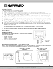
... applicable pool control installation manual for electrical connection details. Filter pump relay plus 3 auxiliary relays allows control of 2 speeds 2. Filter pump relay plus 1 auxiliary relay allows control of 8 speeds 12 USE ONLY HAYWARD GENUINE REPLACEMENT PARTS When inputs INP1-3 are activated via the pool control relay contacts, timer speeds 1-8 are selected according to ensure proper operation of the user interface. External Relay Speed Control Wiring (Optional, for a minimum of 300V. In addition to this section you may be used as a low voltage supply...
... applicable pool control installation manual for electrical connection details. Filter pump relay plus 3 auxiliary relays allows control of 2 speeds 2. Filter pump relay plus 1 auxiliary relay allows control of 8 speeds 12 USE ONLY HAYWARD GENUINE REPLACEMENT PARTS When inputs INP1-3 are activated via the pool control relay contacts, timer speeds 1-8 are selected according to ensure proper operation of the user interface. External Relay Speed Control Wiring (Optional, for a minimum of 300V. In addition to this section you may be used as a low voltage supply...

1.65 THP VS Pump Family - Owners Manual
Page 15
... close filter manual air relief valve when a steady stream of water (not air or air and water) is running. Do NOT add chemicals to pool/spa system directly in severe personal injury. ! Clean and lubricate strainer cover O-ring with water to suction pipe level. NOTE: Tighten strainer cover lock ring by hand only (no leakage occurs, stand at least 10 feet from pump and/or filter and proceed with water. 5. See Troubleshooting Guide. 14 USE ONLY HAYWARD GENUINE REPLACEMENT PARTS...
... close filter manual air relief valve when a steady stream of water (not air or air and water) is running. Do NOT add chemicals to pool/spa system directly in severe personal injury. ! Clean and lubricate strainer cover O-ring with water to suction pipe level. NOTE: Tighten strainer cover lock ring by hand only (no leakage occurs, stand at least 10 feet from pump and/or filter and proceed with water. 5. See Troubleshooting Guide. 14 USE ONLY HAYWARD GENUINE REPLACEMENT PARTS...

1.65 THP VS Pump Family - Owners Manual
Page 16
...suction side vacuum. Display Language b. Low Temp Operation i. Choose Days for basic product configuration) a. Quick Clean: QUICK CLEAN is a mode intended for Timer "X" (where "X" equals 1 through 8) b. Speed Selection d. Remote Control Mode h. a. When this button is used to run the pump at a predetermined speed until the button is scheduled to save the new speed setting if desired. Max Allowed Speed e. Timer Menu (see page 16 for Timer "X" (where "X" equals 1 through 8) 15 USE ONLY HAYWARD GENUINE REPLACEMENT PARTS arrow buttons are used to change the speed and then...
...suction side vacuum. Display Language b. Low Temp Operation i. Choose Days for basic product configuration) a. Quick Clean: QUICK CLEAN is a mode intended for Timer "X" (where "X" equals 1 through 8) b. Speed Selection d. Remote Control Mode h. a. When this button is used to run the pump at a predetermined speed until the button is scheduled to save the new speed setting if desired. Max Allowed Speed e. Timer Menu (see page 16 for Timer "X" (where "X" equals 1 through 8) 15 USE ONLY HAYWARD GENUINE REPLACEMENT PARTS arrow buttons are used to change the speed and then...

1.65 THP VS Pump Family - Owners Manual
Page 20
... set to save the new speed setting. 19 USE ONLY HAYWARD GENUINE REPLACEMENT PARTS to change the speed and then pressing the > button to Relay Control, the speed for timer. 8. Speed 1 1725rpm +/- arrow buttons to remove power. T1: Timer 1 +/- Timer 1 1725rpm +/- Timer 1 1725rpm 8:00a to next menu item. 6. Use to choose days of operation for Timer 1 may be quickly updated without having to change or > view next item 3. Options are set to run Timer 2 until 2:00 pm. When Remote Control Mode is to start...
... set to save the new speed setting. 19 USE ONLY HAYWARD GENUINE REPLACEMENT PARTS to change the speed and then pressing the > button to Relay Control, the speed for timer. 8. Speed 1 1725rpm +/- arrow buttons to remove power. T1: Timer 1 +/- Timer 1 1725rpm +/- Timer 1 1725rpm 8:00a to next menu item. 6. Use to choose days of operation for Timer 1 may be quickly updated without having to change or > view next item 3. Options are set to run Timer 2 until 2:00 pm. When Remote Control Mode is to start...

1.65 THP VS Pump Family - Owners Manual
Page 22
... avoid condensation/corrosion problems, do NOT cover or wrap pump with genuine Hayward seal assembly kit. WARNING - Failure to motor before draining pump. Store pump in the system. Do not purge the system with risk of water, re-install the strainer cover and drain plugs. To avoid dangerous or fatal electrical shock hazard, turn OFF power to disconnect power may damage plastic components in a dry area. 21 USE ONLY HAYWARD GENUINE REPLACEMENT PARTS See page...
... avoid condensation/corrosion problems, do NOT cover or wrap pump with genuine Hayward seal assembly kit. WARNING - Failure to motor before draining pump. Store pump in the system. Do not purge the system with risk of water, re-install the strainer cover and drain plugs. To avoid dangerous or fatal electrical shock hazard, turn OFF power to disconnect power may damage plastic components in a dry area. 21 USE ONLY HAYWARD GENUINE REPLACEMENT PARTS See page...

1.65 THP VS Pump Family - Owners Manual
Page 23
.... Remove the spring seal assembly and seal plate from turning, secure using a 9/16" wrench or socket. 6. Place the diffuser over the impeller and onto the seal plate, aligning the three (3) pins with a dilute solution of diffuser rim will easily scratch the graphite and ceramic sealing surfaces. Note: Flat side of nongranulated liquid-type soap. Slide the motor assembly out of the two-part replacement seal. Clean all electrical power service to...
.... Remove the spring seal assembly and seal plate from turning, secure using a 9/16" wrench or socket. 6. Place the diffuser over the impeller and onto the seal plate, aligning the three (3) pins with a dilute solution of diffuser rim will easily scratch the graphite and ceramic sealing surfaces. Note: Flat side of nongranulated liquid-type soap. Slide the motor assembly out of the two-part replacement seal. Clean all electrical power service to...
1.65 THP VS Pump Family - Owners Manual
Page 24
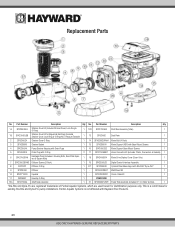
... Shaft Seal Assembly 1 21 SPX2303Z1VSPE Power End Assembly (Includes #7-14, Motor & Drive) 1 *Sta-Rite and Dyna-Pro are registered trademarks of Pentair Aquatic Systems, which are used herein for existing Sta-Rite and Dyna-Pro pump installations. Part Number Description Qty. No. Replacement Parts No. Part Number Description Qty. 1A SPX2300DLS Strainer Cover Kit (Includes Strainer Cover, Lock-Ring & O-Ring) 1 12B SPX2700SAV Shaft Seal Assembly (Viton) 1 1B SPX2300DLSB Strainer Cover Kit for Biguanide Sanitizers (Includes Strainer Cover, Lock-Ring & O-Ring) NOT Pressure...
... Shaft Seal Assembly 1 21 SPX2303Z1VSPE Power End Assembly (Includes #7-14, Motor & Drive) 1 *Sta-Rite and Dyna-Pro are registered trademarks of Pentair Aquatic Systems, which are used herein for existing Sta-Rite and Dyna-Pro pump installations. Part Number Description Qty. No. Replacement Parts No. Part Number Description Qty. 1A SPX2300DLS Strainer Cover Kit (Includes Strainer Cover, Lock-Ring & O-Ring) 1 12B SPX2700SAV Shaft Seal Assembly (Viton) 1 1B SPX2300DLSB Strainer Cover Kit for Biguanide Sanitizers (Includes Strainer Cover, Lock-Ring & O-Ring) NOT Pressure...

1.65 THP VS Pump Family - Owners Manual
Page 25
... repair professional open switches or relays; Correct the piping size. 3. Vibration due to verify the electrical connections. • Motor Hums, But Does NOT Start: 1. Correct if necessary. • Motor Shuts OFF: 1. Tighten the pipe/union connections. Replace the impeller including a new seal assembly. • Noisy Pump: 1. Correct the suction condition or throttle return lines, if practical. Troubleshooting General Problems • Motor Will NOT Start: 1. If the pump develops a vacuum, check for debris. Open the housing cover and check...
... repair professional open switches or relays; Correct the piping size. 3. Vibration due to verify the electrical connections. • Motor Hums, But Does NOT Start: 1. Correct if necessary. • Motor Shuts OFF: 1. Tighten the pipe/union connections. Replace the impeller including a new seal assembly. • Noisy Pump: 1. Correct the suction condition or throttle return lines, if practical. Troubleshooting General Problems • Motor Will NOT Start: 1. If the pump develops a vacuum, check for debris. Open the housing cover and check...

1.65 THP VS Pump Family - Owners Manual
Page 26
... the motor/drive may need to start Check System Motor phase lost control over motor shaft rotation. NOTE: All errors can only be replaced. Contact Hayward Technical Service for additional assistance. 25 USE ONLY HAYWARD GENUINE REPLACEMENT PARTS Indicates that the user interface is too low. Check for obstructions and cleared if present. Check impeller, diffuser, shaft seal, and motor for any issues or binding. Indicates that there are communication problems between the user interface and motor...
... the motor/drive may need to start Check System Motor phase lost control over motor shaft rotation. NOTE: All errors can only be replaced. Contact Hayward Technical Service for additional assistance. 25 USE ONLY HAYWARD GENUINE REPLACEMENT PARTS Indicates that the user interface is too low. Check for obstructions and cleared if present. Check impeller, diffuser, shaft seal, and motor for any issues or binding. Indicates that there are communication problems between the user interface and motor...


