Operation Manual
Page 2
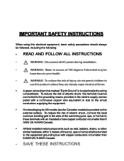
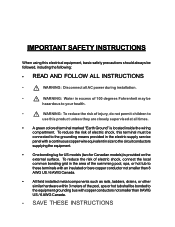
... closely supervised at all AC power during installation. • ! To reduce the risk of electric shock, this terminal must be connected to the grounding means provided in the electric supply service panel with a continuous copper wire equivalent in excess of 100 degrees Fahrenheit may be hazardous to your health. • ! IMPORTANT SAFETY INSTRUCTIONS When using this electrical equipment, basic safety precautions...
... closely supervised at all AC power during installation. • ! To reduce the risk of electric shock, this terminal must be connected to the grounding means provided in the electric supply service panel with a continuous copper wire equivalent in excess of 100 degrees Fahrenheit may be hazardous to your health. • ! IMPORTANT SAFETY INSTRUCTIONS When using this electrical equipment, basic safety precautions...
Operation Manual
Page 3
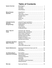
... Flow Switch 40 Cell, Water, Air, Solar Temperature 40 Software Revision 40 Warranty Aqua Logic Warranty 42 Manually 30 Operate the Spa - Automatically 30 Set the Heater Temperature 30 Set the Chlorinator Output 30 Start/Stop Superchlorination 31 Program a Timeclock 31 Program a Countdown Timer 31 Enter/Exit Service Mode 32 Chlorinator Operation/ Water Chemistry Saturation Index 33 Salt Level 34 Type of Contents Block Diagram 1 Automation 1 Chlorination 2 Default Display 2 Manual System Operation Output Names 3 Filter Pump 3 Lights and Aux Outputs 4 Pool/Spa Valves...
... Flow Switch 40 Cell, Water, Air, Solar Temperature 40 Software Revision 40 Warranty Aqua Logic Warranty 42 Manually 30 Operate the Spa - Automatically 30 Set the Heater Temperature 30 Set the Chlorinator Output 30 Start/Stop Superchlorination 31 Program a Timeclock 31 Program a Countdown Timer 31 Enter/Exit Service Mode 32 Chlorinator Operation/ Water Chemistry Saturation Index 33 Salt Level 34 Type of Contents Block Diagram 1 Automation 1 Chlorination 2 Default Display 2 Manual System Operation Output Names 3 Filter Pump 3 Lights and Aux Outputs 4 Pool/Spa Valves...
Operation Manual
Page 4
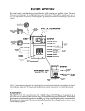
... a display/keypad which is important to system setup are available. Optional Wireless Spaside Remote G LDLINE C O N TR O L S IN C . All of three) INPUT Water Temperature Sensors Air Solar Chlorinator Flow Switch Circuit Breaker Subpanel 240 VAC Power OUTPUT Filter Pump Lights Aux (2 (6 for for the PS-16) automatic valve actuators, and 2 conventional heaters plus a solar heater. System Overview The Aqua Logic is a multifunction pool controller used with PS-16 only) 240 VAC Power OUTPUT 120/240V Aux (8) Relays General Purpose 24V Valve Valves (4) Actuators...
... a display/keypad which is important to system setup are available. Optional Wireless Spaside Remote G LDLINE C O N TR O L S IN C . All of three) INPUT Water Temperature Sensors Air Solar Chlorinator Flow Switch Circuit Breaker Subpanel 240 VAC Power OUTPUT Filter Pump Lights Aux (2 (6 for for the PS-16) automatic valve actuators, and 2 conventional heaters plus a solar heater. System Overview The Aqua Logic is a multifunction pool controller used with PS-16 only) 240 VAC Power OUTPUT 120/240V Aux (8) Relays General Purpose 24V Valve Valves (4) Actuators...
Operation Manual
Page 7
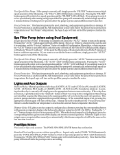
... continuously. Lights and Aux Outputs Standard Relay: Manual operation of 20%. When the desired output level is identical. The "Filter" LED will flash. If Freeze Protection is enabled and the AIR temperature sensor falls below the preset freeze protection temperature, the Aqua Logic will automatically turn off , press the "AUX1" button to turn off the pump. The "AUX1" LED will turn on the filter pump to circulate the water. AUX14 for a PS-16 model) is displayed, press...
... continuously. Lights and Aux Outputs Standard Relay: Manual operation of 20%. When the desired output level is identical. The "Filter" LED will flash. If Freeze Protection is enabled and the AIR temperature sensor falls below the preset freeze protection temperature, the Aqua Logic will automatically turn off , press the "AUX1" button to turn off the pump. The "AUX1" LED will turn on the filter pump to circulate the water. AUX14 for a PS-16 model) is displayed, press...
Operation Manual
Page 15
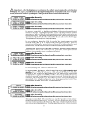
... programmed spa temperature. The Aqua Logic allows more information). For pool/spa combination systems with "Filter Hi"). For two speed pumps, this time period, the filter pump will operate in the display will be replaced with spillover enabled and filter operation set to "pool only", the valves will automatically switch to spillover mode at times other than the timeclock period set to "spillover", the valves will switch to prime and establish water flow. There are several reasons the filter pump...
... programmed spa temperature. The Aqua Logic allows more information). For pool/spa combination systems with "Filter Hi"). For two speed pumps, this time period, the filter pump will operate in the display will be replaced with spillover enabled and filter operation set to "pool only", the valves will automatically switch to spillover mode at times other than the timeclock period set to "spillover", the valves will switch to prime and establish water flow. There are several reasons the filter pump...

Operation Manual
Page 16
... manual operation of the filter button or pool/spa valve button will automatically switch to program those separately (see below ). Lights-CountDn 0:20 + Adjust time setting (Manual On/Off, 0:05, 0:10, 0:015...) > Move to previous/next menu item This menu will appear only if the Lights are configured for countdown timer. For one speed pumps, this function is the time after you will turn on or and off control by pressing the LIGHTS button...
... manual operation of the filter button or pool/spa valve button will automatically switch to program those separately (see below ). Lights-CountDn 0:20 + Adjust time setting (Manual On/Off, 0:05, 0:10, 0:015...) > Move to previous/next menu item This menu will appear only if the Lights are configured for countdown timer. For one speed pumps, this function is the time after you will turn on or and off control by pressing the LIGHTS button...
Operation Manual
Page 17
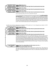
... be operated when the filter pump is running and the pool/spa valves are in the display will be because of the programmed low speed time period. These include manual operation or heating operation. For PS-4, Aux1 and Aux2 configurations are several reasons why the pump will automatically switch to high speed operation during the programmed off the relay at the designated times. Aux14 configurations are identical. Also, manual operation overrides the timeclock. > > > > > > > SSeptaDFailytearndT2Ti-malel + Adjust time setting...
... be operated when the filter pump is running and the pool/spa valves are in the display will be because of the programmed low speed time period. These include manual operation or heating operation. For PS-4, Aux1 and Aux2 configurations are several reasons why the pump will automatically switch to high speed operation during the programmed off the relay at the designated times. Aux14 configurations are identical. Also, manual operation overrides the timeclock. > > > > > > > SSeptaDFailytearndT2Ti-malel + Adjust time setting...

Operation Manual
Page 20
.... PS-8 and PS-16 Virtual Models Aqua Logic Virtual models are T-CELL-5 or T-CELL-15 (default). If disabled (default), then neither the cell nor flow switch need to be installed and all displays relating to the AQL-PS-4 with 4 additional Aux outputs. Refer to the following pages for information on virtual models can be programmed to 40,000 gallons. 17 Changing the Super Chlorinate state using the Settings Menu, the Aqua Pod Super Chlorinate button, or a Super Chlorinate assigned Aux/Lights/Valve button...
.... PS-8 and PS-16 Virtual Models Aqua Logic Virtual models are T-CELL-5 or T-CELL-15 (default). If disabled (default), then neither the cell nor flow switch need to be installed and all displays relating to the AQL-PS-4 with 4 additional Aux outputs. Refer to the following pages for information on virtual models can be programmed to 40,000 gallons. 17 Changing the Super Chlorinate state using the Settings Menu, the Aqua Pod Super Chlorinate button, or a Super Chlorinate assigned Aux/Lights/Valve button...
Operation Manual
Page 22
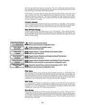
... to the filter relay. See the Operation manual for specific information regarding the control logic for 35 seconds whenever the Pool/Spa valves are turning. When used with a Goldline flow switch, the Aqua Logic monitors the state of names (e.g. This option is set to previous/next configuration menu Filter Name The Aqua Logic allows you have assigned. Filter Off Valve Change This menu appears only if Pool/Spa setup is usually preferable because both the pool and spa water will be filtered and sanitized...
... to the filter relay. See the Operation manual for specific information regarding the control logic for 35 seconds whenever the Pool/Spa valves are turning. When used with a Goldline flow switch, the Aqua Logic monitors the state of names (e.g. This option is set to previous/next configuration menu Filter Name The Aqua Logic allows you have assigned. Filter Off Valve Change This menu appears only if Pool/Spa setup is usually preferable because both the pool and spa water will be filtered and sanitized...
Operation Manual
Page 45
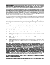
... used in product's owners manual(s). 4. Problems resulting from improper installation including installation on pools larger than the product rating. 3. For residential installations in USA or Canada: If a product is defective in process of installation. 2. THIS WARRANTY GIVES YOU SPECIFIC LEGAL RIGHTS, AND YOU MAYALSO HAVE OTHER RIGHTS WHICH VARYFROM STATE TO STATE. LIMITED WARRANTY Goldline warrants its Aqua Rite, Aqua Rite Pro, Aqua Trol, Aqua Logic and Pro Logic products (products with Goldline part numbers starting with AQ-RITE...
... used in product's owners manual(s). 4. Problems resulting from improper installation including installation on pools larger than the product rating. 3. For residential installations in USA or Canada: If a product is defective in process of installation. 2. THIS WARRANTY GIVES YOU SPECIFIC LEGAL RIGHTS, AND YOU MAYALSO HAVE OTHER RIGHTS WHICH VARYFROM STATE TO STATE. LIMITED WARRANTY Goldline warrants its Aqua Rite, Aqua Rite Pro, Aqua Trol, Aqua Logic and Pro Logic products (products with Goldline part numbers starting with AQ-RITE...
Installation Manual
Page 2
... electric supply service panel with a continuous copper wire equivalent in size to the circuit conductors supplying the equipment. • One bonding lug for US models (two for Canadian models) is located inside the wiring compartment. To reduce the risk of electric shock, connect the local common bonding grid in excess of electric shock, this product unless they are closely supervised at all AC power during installation...
... electric supply service panel with a continuous copper wire equivalent in size to the circuit conductors supplying the equipment. • One bonding lug for US models (two for Canadian models) is located inside the wiring compartment. To reduce the risk of electric shock, connect the local common bonding grid in excess of electric shock, this product unless they are closely supervised at all AC power during installation...
Installation Manual
Page 4
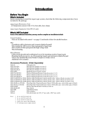
... filter pump and other high voltage loads Wire for bonding Miscellaneous Utility electrical outlet and weatherproof cover (for use standard Hayward, Pentair/Compool, or Jandy valves) Additional valve actuators Accessory Products - seal)) Notes: 1. Introduction Before You Begin What's Included Before attempting to install the Aqua Logic system, check that you may need to complete an installation include: Circuit breakers None are included with control-see note 4) AQL2-BASE-RF Base Station AQL-DIM Light Dimmer Relay...
... filter pump and other high voltage loads Wire for bonding Miscellaneous Utility electrical outlet and weatherproof cover (for use standard Hayward, Pentair/Compool, or Jandy valves) Additional valve actuators Accessory Products - seal)) Notes: 1. Introduction Before You Begin What's Included Before attempting to install the Aqua Logic system, check that you may need to complete an installation include: Circuit breakers None are included with control-see note 4) AQL2-BASE-RF Base Station AQL-DIM Light Dimmer Relay...

Installation Manual
Page 5
... Remote display/keypad (optional) Temperature sensors Valve actuators (if applicable) 3. System Startup and checkout (page 36) 2 Electrical Wiring (page 13) Main service Grounding and bonding Circuit breakers Aqua Logic control power High Voltage pool equipment Low voltage wiring (temperature sensors, flow switch, etc.) 5. Plumbing (page 9) General Pool Equipment Turbo Cell Flow Switch 4. Installation Steps Details on each installation step are presented on the following pages: 1. NOTE: Before installing this product as part of a saline water purification system in a pool or spa using...
... Remote display/keypad (optional) Temperature sensors Valve actuators (if applicable) 3. System Startup and checkout (page 36) 2 Electrical Wiring (page 13) Main service Grounding and bonding Circuit breakers Aqua Logic control power High Voltage pool equipment Low voltage wiring (temperature sensors, flow switch, etc.) 5. Plumbing (page 9) General Pool Equipment Turbo Cell Flow Switch 4. Installation Steps Details on each installation step are presented on the following pages: 1. NOTE: Before installing this product as part of a saline water purification system in a pool or spa using...
Installation Manual
Page 9
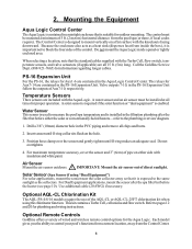
... Cell, flow switch, temperature sensors, and valve actuators (if applicable) are included with the knockouts facing downward. 2. Mounting the Equipment Aqua Logic Control Center The Aqua Logic is enabled. The relays for outdoor mounting. Insert sensor until O-ring makes an adequate seal. Position hose clamp over the sensor and gently tighten until O-ring collar sits flush on a flat surface with the Aqua Logic. Air Sensor Mount the air sensor outdoors. ! Solar Sensor (Spa Sensor if using the chlorinator function. This kit contains a Turbo Cell, cell...
... Cell, flow switch, temperature sensors, and valve actuators (if applicable) are included with the knockouts facing downward. 2. Mounting the Equipment Aqua Logic Control Center The Aqua Logic is enabled. The relays for outdoor mounting. Insert sensor until O-ring makes an adequate seal. Position hose clamp over the sensor and gently tighten until O-ring collar sits flush on a flat surface with the Aqua Logic. Air Sensor Mount the air sensor outdoors. ! Solar Sensor (Spa Sensor if using the chlorinator function. This kit contains a Turbo Cell, cell...

Installation Manual
Page 16
...L1 Expansion Unit (AQL-PS-16 only) Bonding Lug(s) The Aqua Logic Control Center and PS-16 Expansion Unit require both high and low voltage connections. Electrical Wiring 3 Temp Sensor Inputs 4 wire connection between PS-16 and -EXP Remote Display/Keypad Connector Wireless Base Receiver Connector "Local" Display 2 Heater Outputs 4 4 Valve Connectors 3 2 1 Flow Switch Connector Cell Connector 8 High Voltage Relays for PS-8, PS-16 (4 relays for wiring. SUITABLE LISTED BREAKERS Manufacturer Single Double Twin Quad GFCB Filler Plates Cutler-Hammer Murray Siemens Square...
...L1 Expansion Unit (AQL-PS-16 only) Bonding Lug(s) The Aqua Logic Control Center and PS-16 Expansion Unit require both high and low voltage connections. Electrical Wiring 3 Temp Sensor Inputs 4 wire connection between PS-16 and -EXP Remote Display/Keypad Connector Wireless Base Receiver Connector "Local" Display 2 Heater Outputs 4 4 Valve Connectors 3 2 1 Flow Switch Connector Cell Connector 8 High Voltage Relays for PS-8, PS-16 (4 relays for wiring. SUITABLE LISTED BREAKERS Manufacturer Single Double Twin Quad GFCB Filler Plates Cutler-Hammer Murray Siemens Square...
Installation Manual
Page 18
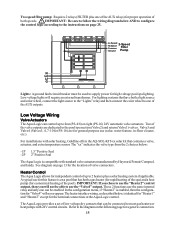
... the wiring diagram below AND to configure the control logic according to supply power for high voltage pool/spa lighting. Low voltage lights will not be enabled. See diagram on page 25. Lo Speed Hi Speed Common 2-Speed Filter Ground Pump N L2 L1 G Lights: A ground fault circuit breaker must be connected to 2 heaters plus one of the AUX relays) for proper operation of valve connectors. For installations with solar heating, Goldline offers the AQ-SOL-KIT-xx solar kit that have both a light source and color wheel, connect the light...
... the wiring diagram below AND to configure the control logic according to supply power for high voltage pool/spa lighting. Low voltage lights will not be enabled. See diagram on page 25. Lo Speed Hi Speed Common 2-Speed Filter Ground Pump N L2 L1 G Lights: A ground fault circuit breaker must be connected to 2 heaters plus one of the AUX relays) for proper operation of valve connectors. For installations with solar heating, Goldline offers the AQ-SOL-KIT-xx solar kit that have both a light source and color wheel, connect the light...
Installation Manual
Page 19
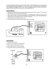
..., use 105°C rated wire. 3. Wire heater to 120/240V power source per the diagram below. Many internal parts of the heater can get very hot--see the heater manufacturer's recommendations on the heater to the maximum (hottest) setting. Kill Switch Thermostat Pool/Spa Air Solar Heater1 Heater2 Heater Ignition/Valve Laars Heaters 1. Wire Aqua Logic to the heater as "2-wire" remote control). Set the thermostat(s) on the minimum temperature rating for wires. Remove factory jumper from terminal block. 3. For millivolt or line voltage heaters, contact Goldline Tech support...
..., use 105°C rated wire. 3. Wire heater to 120/240V power source per the diagram below. Many internal parts of the heater can get very hot--see the heater manufacturer's recommendations on the heater to the maximum (hottest) setting. Kill Switch Thermostat Pool/Spa Air Solar Heater1 Heater2 Heater Ignition/Valve Laars Heaters 1. Wire Aqua Logic to the heater as "2-wire" remote control). Set the thermostat(s) on the minimum temperature rating for wires. Remove factory jumper from terminal block. 3. For millivolt or line voltage heaters, contact Goldline Tech support...

Installation Manual
Page 32
... if solar heat is selected > Move to previous/next menu item or next configuration menu for all functions except dimmer relay, low speed, and group Lights Freeze + Toggle between Enabled and Disabled (default) Lights Freeze Disable > Move to technicians who may be used. A sheet of the pool/spa suction valve, the proper temperature setting will operate normally. If solar is "Enabled", the valve or solar pump relay will turn on when the water temperature is...
... if solar heat is selected > Move to previous/next menu item or next configuration menu for all functions except dimmer relay, low speed, and group Lights Freeze + Toggle between Enabled and Disabled (default) Lights Freeze Disable > Move to technicians who may be used. A sheet of the pool/spa suction valve, the proper temperature setting will operate normally. If solar is "Enabled", the valve or solar pump relay will turn on when the water temperature is...
Installation Manual
Page 41
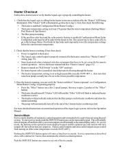
... (Configuration Menu/Solar Config) then solar must be off ) and the "Filter" LED will flash to indicated heater cooldown is active. • The display will continue for the heater to the Operation Manual. Service operation as possible (usually 104ºF/40ºC). Service Mode Service mode disables all outputs off at least 2ºF greater than the water temperature (Settings Menu / Pool Heater & Spa Heater). • The filter pump is on . see "Heater Control" wiring, page 15). • Some heaters also have internal switches...
... (Configuration Menu/Solar Config) then solar must be off ) and the "Filter" LED will flash to indicated heater cooldown is active. • The display will continue for the heater to the Operation Manual. Service operation as possible (usually 104ºF/40ºC). Service Mode Service mode disables all outputs off at least 2ºF greater than the water temperature (Settings Menu / Pool Heater & Spa Heater). • The filter pump is on . see "Heater Control" wiring, page 15). • Some heaters also have internal switches...
Installation Manual
Page 43
... SUCH DAMAGES. For commercial installations, installations outside of the USA or Canada and for warranty service. Problems resulting from failure to maintain pool water chemistry in accordance with the recommendations in process of installation. 2. LIMITED WARRANTY Goldline warrants its Aqua Rite, Aqua Rite Pro, Aqua Trol, Aqua Logic and Pro Logic products (products with Goldline part numbers starting with AQ-RITE-, AQ-RT-PRO, AQ-TROL-, AQ-LOGIC-, AQL-P-, AQL-PS-, AQL-CL-, PL-P-, PL-PS-, and HPC-2) to be...
... SUCH DAMAGES. For commercial installations, installations outside of the USA or Canada and for warranty service. Problems resulting from failure to maintain pool water chemistry in accordance with the recommendations in process of installation. 2. LIMITED WARRANTY Goldline warrants its Aqua Rite, Aqua Rite Pro, Aqua Trol, Aqua Logic and Pro Logic products (products with Goldline part numbers starting with AQ-RITE-, AQ-RT-PRO, AQ-TROL-, AQ-LOGIC-, AQL-P-, AQL-PS-, AQL-CL-, PL-P-, PL-PS-, and HPC-2) to be...


