HCP Series LITCPOMA10
Page 2
... 2.3 Nameplate Ratings 2.4 Liability 2.5 Standards 2.6 General Instructions in Relation to the Main Power Supply 6.1 Electrical 6.2 Voltage 6.3 Emergency Shutoff 6.4 Grounding/Bonding 6.5 Wiring 6.6 Engineering Specs 2 Suction Lift Installation 5.4 HCP Pump Piping - Flooded Installation 6. Connection to User Safety 3. Dimensions 4. Description 1.1 HCP Series Self-Priming Centrifugal Pump and Trap 1.2 Technical Characteristics 2. TABLE OF CONTENTS Table of Contents 1.
... 2.3 Nameplate Ratings 2.4 Liability 2.5 Standards 2.6 General Instructions in Relation to the Main Power Supply 6.1 Electrical 6.2 Voltage 6.3 Emergency Shutoff 6.4 Grounding/Bonding 6.5 Wiring 6.6 Engineering Specs 2 Suction Lift Installation 5.4 HCP Pump Piping - Flooded Installation 6. Connection to User Safety 3. Dimensions 4. Description 1.1 HCP Series Self-Priming Centrifugal Pump and Trap 1.2 Technical Characteristics 2. TABLE OF CONTENTS Table of Contents 1.

HCP Series LITCPOMA10
Page 3
General 7.6 Piping - Strainer 8. Troubleshooting 12. Exploded Diagram 3 Suction 7.7 Piping - Discharge 7.8 Piping - Assembly/Disassembly/Parts List 11. Start-Up and Operation 8.1 Prior to Start-Up 8.2 Starting/Priming the Pump 8.3 Maintenance 8.4 Storage/Winterization 8.5 Storing Pump for Winterization 9. 7. Pump Suction Requirements 7.1 Entrapment Protection 7.2 Suction Outlet Covers 7.3 Outlets Per Pump 7.4 Water Velocity and Flow Rates 7.5 Piping - Maintenance/Conservation - Strainer 10. Illustrations and Electrical Drawings 13.
General 7.6 Piping - Strainer 8. Troubleshooting 12. Exploded Diagram 3 Suction 7.7 Piping - Discharge 7.8 Piping - Assembly/Disassembly/Parts List 11. Start-Up and Operation 8.1 Prior to Start-Up 8.2 Starting/Priming the Pump 8.3 Maintenance 8.4 Storage/Winterization 8.5 Storing Pump for Winterization 9. 7. Pump Suction Requirements 7.1 Entrapment Protection 7.2 Suction Outlet Covers 7.3 Outlets Per Pump 7.4 Water Velocity and Flow Rates 7.5 Piping - Maintenance/Conservation - Strainer 10. Illustrations and Electrical Drawings 13.
HCP Series LITCPOMA10
Page 4
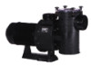
.... its use with cast iron housings. Description 1.1 HCP SERIES SELF-PRIMING CENTRIFUGAL PUMP AND TRAP - durable, reliable. HCP pumps are made from glass-reinforced Noryl™. This manual should be furnished to traditional pumps with commercial swimming pools or as a centrifugal pump. Is an excellent performer; The Hayward HCP Series Self-Priming Centrifugal Pump is designed for use will reduce service...
.... its use with cast iron housings. Description 1.1 HCP SERIES SELF-PRIMING CENTRIFUGAL PUMP AND TRAP - durable, reliable. HCP pumps are made from glass-reinforced Noryl™. This manual should be furnished to traditional pumps with commercial swimming pools or as a centrifugal pump. Is an excellent performer; The Hayward HCP Series Self-Priming Centrifugal Pump is designed for use will reduce service...
HCP Series LITCPOMA10
Page 5
... readily disassembled for storage and reassembled to the functioning of the following signal words and be readily disassembled for personal injury. This pump is constructed so that will cause death, serious personal injury, or major property damage if ignored. A storable pool is for...property damage if ignored. In order to obtain the maximum performance shown by the following : To reduce the risk of the HCP Series Self-Priming Pumps. ATTENTION Other instructions in the Description, it cannot be alert to install and service this manual, look for installation, use...
... readily disassembled for storage and reassembled to the functioning of the following signal words and be readily disassembled for personal injury. This pump is constructed so that will cause death, serious personal injury, or major property damage if ignored. A storable pool is for...property damage if ignored. In order to obtain the maximum performance shown by the following : To reduce the risk of the HCP Series Self-Priming Pumps. ATTENTION Other instructions in the Description, it cannot be alert to install and service this manual, look for installation, use...

HCP Series LITCPOMA10
Page 6
...8226; Limit test to the choice, handling, installation, starting and maintenance of the warranty. 2.5 STANDARDS Our HCP Series pumps are manufactured in system before operating or testing equipment. For non-Hayward equipment, consult manufacturer. 2.3 NAMEPLATE RATINGS The information given on the nameplate, or other installations and, in...given by hand only. See pages 14-15. 5. Trapped air in relation to 24 hours. Do not connect system to Hayward equipment only. and ELECTRICAL SPECIFICATIONS, section 3.2. 2.4 LIABILITY Failure to be found in this manual, in system can be ...
...8226; Limit test to the choice, handling, installation, starting and maintenance of the warranty. 2.5 STANDARDS Our HCP Series pumps are manufactured in system before operating or testing equipment. For non-Hayward equipment, consult manufacturer. 2.3 NAMEPLATE RATINGS The information given on the nameplate, or other installations and, in...given by hand only. See pages 14-15. 5. Trapped air in relation to 24 hours. Do not connect system to Hayward equipment only. and ELECTRICAL SPECIFICATIONS, section 3.2. 2.4 LIABILITY Failure to be found in this manual, in system can be ...
HCP Series LITCPOMA10
Page 8
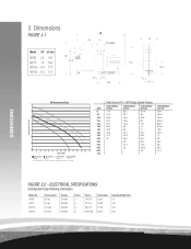
...300 350 400 450 500 550 600 650 700 F low (G P M ) PERFORMANCE - PERFORMANCE - Head Loss in Ft - ELECTRICAL SPECIFICATIONS: Commercial Pump Ordering Information Model No. HCP55 HCP75 HCP100 HCP125 Horse-power 5.5 hp 7.5 hp 10.0 hp 12.5 hp Voltage 230/460 230/460 230/460 ...51.9 58 600 33 45.33 53.2 650 38 47.4 700 FIGURE 3.2 - PERFORMACE - DIMENSIONS Total Dynamic Head (Ft) 3. PERFORMANCE - HCP Single Speed Pumps PERFORMACE - PERFORMACE - HCP55 HCP75 HCP100 HCP125 All motors: Certified to UL 1004, IP 55 protection, insulation class F. 60 hz., 3.550 ...
...300 350 400 450 500 550 600 650 700 F low (G P M ) PERFORMANCE - PERFORMANCE - Head Loss in Ft - ELECTRICAL SPECIFICATIONS: Commercial Pump Ordering Information Model No. HCP55 HCP75 HCP100 HCP125 Horse-power 5.5 hp 7.5 hp 10.0 hp 12.5 hp Voltage 230/460 230/460 230/460 ...51.9 58 600 33 45.33 53.2 650 38 47.4 700 FIGURE 3.2 - PERFORMACE - DIMENSIONS Total Dynamic Head (Ft) 3. PERFORMANCE - HCP Single Speed Pumps PERFORMACE - PERFORMACE - HCP55 HCP75 HCP100 HCP125 All motors: Certified to UL 1004, IP 55 protection, insulation class F. 60 hz., 3.550 ...

HCP Series LITCPOMA10
Page 9
...temperatures. ATTENTION The user, upon receipt of serious deterioration, he shall also formally notify the supplier within a period not exceeding 8 days from pump and strainer. ATTENTION Storage conditions must be sure that it is not damaged during transport or storage thus preventing its particular relevance, we must stress... check the following points: • Condition of the equipment. Due to work on it cool before trying to collect around the pump motor. If necessary, clean with carrier immediately. Remove all threaded joints and mating surfaces are heavy.
...temperatures. ATTENTION The user, upon receipt of serious deterioration, he shall also formally notify the supplier within a period not exceeding 8 days from pump and strainer. ATTENTION Storage conditions must be sure that it is not damaged during transport or storage thus preventing its particular relevance, we must stress... check the following points: • Condition of the equipment. Due to work on it cool before trying to collect around the pump motor. If necessary, clean with carrier immediately. Remove all threaded joints and mating surfaces are heavy.
HCP Series LITCPOMA10
Page 10
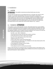
...dismounted horizontally and the air filter vertically (see minimum space diagram in order to prevent flooding. • Be protected from pump. If the pump is important for routine maintenance. 10 INSTALLATION 5. In all events, there must be needed. • Have adequate floor drainage to... prevent the formation of going underwater. Level - It's important to choose an area that has a drain, so that the pump motor will not be a drain in the floor as possible. • Use short, direct suction pipe (to be located must be ...
...dismounted horizontally and the air filter vertically (see minimum space diagram in order to prevent flooding. • Be protected from pump. If the pump is important for routine maintenance. 10 INSTALLATION 5. In all events, there must be needed. • Have adequate floor drainage to... prevent the formation of going underwater. Level - It's important to choose an area that has a drain, so that the pump motor will not be a drain in the floor as possible. • Use short, direct suction pipe (to be located must be ...
HCP Series LITCPOMA10
Page 11
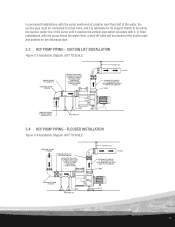
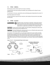
...(TO STABILIZE FLOW) FROM NEAREST FITTING TO STRAINER. NOT TO SCALE. MAXIMUM SUCTION LIFT 10'. 4" UNION SUPPORT PIPE 5.4 HCP PUMP PIPING - FLOODED INSTALLATION Figure 5.4 Installation Diagram. SUPPORT PIPE TO FILTER DISCHARGE PIPE DIAMETER 4". FROM POOL SUCTION PLUMBING ISOLATION VALVES FULL OPEN WHEN...permanent installations, with it is advisable for its longest stretch to be placed on the suction pipe and another on the discharge pipe. 5.3 HCP PUMP PIPING - THE DISTANCE TO THE FIRST ELBOW MUST BE AT LEAST 5 TIMES THE PIPE DIAMETER. 4" UNION LONG RADIUS ELBOW PREFERRED 4"...
...(TO STABILIZE FLOW) FROM NEAREST FITTING TO STRAINER. NOT TO SCALE. MAXIMUM SUCTION LIFT 10'. 4" UNION SUPPORT PIPE 5.4 HCP PUMP PIPING - FLOODED INSTALLATION Figure 5.4 Installation Diagram. SUPPORT PIPE TO FILTER DISCHARGE PIPE DIAMETER 4". FROM POOL SUCTION PLUMBING ISOLATION VALVES FULL OPEN WHEN...permanent installations, with it is advisable for its longest stretch to be placed on the suction pipe and another on the discharge pipe. 5.3 HCP PUMP PIPING - THE DISTANCE TO THE FIRST ELBOW MUST BE AT LEAST 5 TIMES THE PIPE DIAMETER. 4" UNION LONG RADIUS ELBOW PREFERRED 4"...
HCP Series LITCPOMA10
Page 12
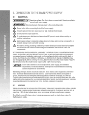
...death. Do not ground to electrical power supply. To avoid dangerous or fatal electrical shock, turn OFF power to electrical shock. HCP Series pumps must be installed by several manufacturers and nameplate data (service factor, maximum amperage, etc.) will vary. Improper installation could create... and electrical codes and requirements. Match supply voltage to correctly choose and size motor starter and control equipment for your pump to nameplate voltage. Consult control manufacturer and motor nameplate on electrical connections. CONNECTION TO THE MAIN POWER SUPPLY 6. Disconnect...
...death. Do not ground to electrical power supply. To avoid dangerous or fatal electrical shock, turn OFF power to electrical shock. HCP Series pumps must be installed by several manufacturers and nameplate data (service factor, maximum amperage, etc.) will vary. Improper installation could create... and electrical codes and requirements. Match supply voltage to correctly choose and size motor starter and control equipment for your pump to nameplate voltage. Consult control manufacturer and motor nameplate on electrical connections. CONNECTION TO THE MAIN POWER SUPPLY 6. Disconnect...
HCP Series LITCPOMA10
Page 13
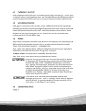
... Ensure that is absolutely necessary to electrical service ground. For this switch and mount it is blocked. do not start the pump if it in suction piping. 6.6 ENGINEERING SPECS See pg. 8 13 Connect motor ground terminal to advise the authorised installer ...Pump should rotate counterclockwise when viewed through pump suction port. ATTENTION Check that the direction of the shaft, on the nameplate rating (80) (fig. 4, page 23); use in case of water in a location that the motor shaft turns freely; Clearly mark this purpose, HCP Series pumps ...
... Ensure that is absolutely necessary to electrical service ground. For this switch and mount it is blocked. do not start the pump if it in suction piping. 6.6 ENGINEERING SPECS See pg. 8 13 Connect motor ground terminal to advise the authorised installer ...Pump should rotate counterclockwise when viewed through pump suction port. ATTENTION Check that the direction of the shaft, on the nameplate rating (80) (fig. 4, page 23); use in case of water in a location that the motor shaft turns freely; Clearly mark this purpose, HCP Series pumps ...

HCP Series LITCPOMA10
Page 14
... or disembowel bathers. The system must be built so that is, there must be at least three feet apart. Pump Suction Requirements Pump suction is running, see "Outlets Per Pump," section 7.3). The centers of the main drains (suction fittings) must have correctly installed, screw-fastened covers ... less unless the outlet complies with covers (see fig. 7.6 & 7.7, page 15), for Suction Fittings For Use in place. 7.3 OUTLETS PER PUMP Provide at least two suction outlets to use or operate swimming pools, spas, or hot tubs if a suction outlet cover is completely blocked. All...
... or disembowel bathers. The system must be built so that is, there must be at least three feet apart. Pump Suction Requirements Pump suction is running, see "Outlets Per Pump," section 7.3). The centers of the main drains (suction fittings) must have correctly installed, screw-fastened covers ... less unless the outlet complies with covers (see fig. 7.6 & 7.7, page 15), for Suction Fittings For Use in place. 7.3 OUTLETS PER PUMP Provide at least two suction outlets to use or operate swimming pools, spas, or hot tubs if a suction outlet cover is completely blocked. All...
HCP Series LITCPOMA10
Page 15
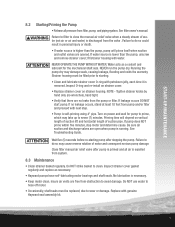
... requires a lower water velocity, comply with the straight side on top. Suction pipe must have valves in pipe. To prevent strain on the pump, support both suction and discharge pipes independently. 7.5 PIPING - Do not block suction. Use larger pipe as required to multiple drains and skimmers ...of non-entrapment design. Recommended Pump Section Layout. 15 See section 5.3. Keep suction pipe clear of severe injury or drowning from hair or body entrapment. Use at least equal...
... requires a lower water velocity, comply with the straight side on top. Suction pipe must have valves in pipe. To prevent strain on the pump, support both suction and discharge pipes independently. 7.5 PIPING - Do not block suction. Use larger pipe as required to multiple drains and skimmers ...of non-entrapment design. Recommended Pump Section Layout. 15 See section 5.3. Keep suction pipe clear of severe injury or drowning from hair or body entrapment. Use at least equal...

HCP Series LITCPOMA10
Page 16
... no longer than 100˚ F (38˚ C). 5. Maximum hydrostatic test pressure is discharged from the valve. 4. Immediately inspect all pump and system components are intact and functioning properly. Fittings restrict flow; STRAINER Hazardous pressure. Center the strainer cover when installing it is ...strainer body, which could result in the system by fully opening filter manual air relief valve until a steady stream of pump/strainer. Run pressure test for best performance use , to prevent leaks. 3. All suction and discharge valves MUST be sure ...
... no longer than 100˚ F (38˚ C). 5. Maximum hydrostatic test pressure is discharged from the valve. 4. Immediately inspect all pump and system components are intact and functioning properly. Fittings restrict flow; STRAINER Hazardous pressure. Center the strainer cover when installing it is ...strainer body, which could result in the system by fully opening filter manual air relief valve until a steady stream of pump/strainer. Run pressure test for best performance use , to prevent leaks. 3. All suction and discharge valves MUST be sure ...
HCP Series LITCPOMA10
Page 17
...ve minutes, stop motor and determine cause. No lubrication is running. Replace with next step. • Pump is discharged from pump and/or filter and proceed with genuine Hayward seal assembly kit. 17 Tighten strainer knobs by hand only (no leakage occurs, stand at least 10 feet... close the manual air relief valve when a steady stream of motor and consequent serious pump damage. Water acts as necessary. • Hayward pumps have self-lubricating motor bearings and shaft seals. Running the pump dry may cause reverse rotation of water (not air or air and water) is ...
...ve minutes, stop motor and determine cause. No lubrication is running. Replace with next step. • Pump is discharged from pump and/or filter and proceed with genuine Hayward seal assembly kit. 17 Tighten strainer knobs by hand only (no leakage occurs, stand at least 10 feet... close the manual air relief valve when a steady stream of motor and consequent serious pump damage. Water acts as necessary. • Hayward pumps have self-lubricating motor bearings and shaft seals. Running the pump dry may cause reverse rotation of water (not air or air and water) is ...

HCP Series LITCPOMA10
Page 18
... toxic and may result in the system. Before removing strainer cover, loosen or remove drain plug in the "off . ATTENTION Allowing the pump to disconnect power may damage plastic components in serious personal injury or death. 1. Regularly check and clean the strainer basket (page 23). ...Drain water level below 5 PSI), high volume blower when air purging the pump, filter, or piping. Purging the system with compressed air can cause components to the pool. 2. Remove drain plugs from mounting pad, wiring...
... toxic and may result in the system. Before removing strainer cover, loosen or remove drain plug in the "off . ATTENTION Allowing the pump to disconnect power may damage plastic components in serious personal injury or death. 1. Regularly check and clean the strainer basket (page 23). ...Drain water level below 5 PSI), high volume blower when air purging the pump, filter, or piping. Purging the system with compressed air can cause components to the pool. 2. Remove drain plugs from mounting pad, wiring...

HCP Series LITCPOMA10
Page 19
... avoid its O-ring seal. For storage of the strainer, remove the basket and clean it under running water; Before starting the pump, replace the drain plug and its deterioration. Loosen the cover of outdoor installation: 1. NOTICE Do not allow interior to compress O-... . To remove strainer cover, unscrew lid bolts. NOTICE A clogged basket will cause cavitation, which will damage strainer basket, impeller, and pump. When installing cover, clean O-Ring surface in chemicals. Lubricate, sealing surfaces of strainer cover O-Rings and body, and threads and faces...
... avoid its O-ring seal. For storage of the strainer, remove the basket and clean it under running water; Before starting the pump, replace the drain plug and its deterioration. Loosen the cover of outdoor installation: 1. NOTICE Do not allow interior to compress O-... . To remove strainer cover, unscrew lid bolts. NOTICE A clogged basket will cause cavitation, which will damage strainer basket, impeller, and pump. When installing cover, clean O-Ring surface in chemicals. Lubricate, sealing surfaces of strainer cover O-Rings and body, and threads and faces...

HCP Series LITCPOMA10
Page 20
... this falls into the correct space. Assembly/Disassembly ATTENTION Before performing any spare parts, indication must be given of the pump with water beforehand. • Assemble the impeller on the junction box (fig. 4, page 23). • Release the plumbing connections. ...• Empty the pump, loosening the drain plugs with the impeller. In order to dismount and disassemble the pump, please see the detail drawing (fig. 4, page 23). ATTENTION In order to assemble the pump: • Assemble the mechanical seal, (fig. 4, page ...
... this falls into the correct space. Assembly/Disassembly ATTENTION Before performing any spare parts, indication must be given of the pump with water beforehand. • Assemble the impeller on the junction box (fig. 4, page 23). • Release the plumbing connections. ...• Empty the pump, loosening the drain plugs with the impeller. In order to dismount and disassemble the pump, please see the detail drawing (fig. 4, page 23). ATTENTION In order to assemble the pump: • Assemble the mechanical seal, (fig. 4, page ...

HCP Series LITCPOMA10
Page 21
...C. FREQUENCY VARIATION Check frequency of controlled clearances. (See Repair Instructions.) D. See Manufacturer's Instructions for disassembly. MECHANICAL A. PUMP NOT PRIMED Reprime. LOOSE PARTS Inspect, repair. 21 FOR VOLTAGE E. OPEN WINDINGS Check leg-to-leg with megohmmeter. ... 5% variation from motor nameplate rating. G. WRONG DIRECTION OF ROTATION Reverse rotation of starter contactor. FLOW THROUGH PUMP COMPLETELY Locate and remove obstruction. OR PARTIALLY OBSTRUCTED B. THERMAL OVERLOAD SWITCH OPEN Check for malfunction. Check circuit ...
...C. FREQUENCY VARIATION Check frequency of controlled clearances. (See Repair Instructions.) D. See Manufacturer's Instructions for disassembly. MECHANICAL A. PUMP NOT PRIMED Reprime. LOOSE PARTS Inspect, repair. 21 FOR VOLTAGE E. OPEN WINDINGS Check leg-to-leg with megohmmeter. ... 5% variation from motor nameplate rating. G. WRONG DIRECTION OF ROTATION Reverse rotation of starter contactor. FLOW THROUGH PUMP COMPLETELY Locate and remove obstruction. OR PARTIALLY OBSTRUCTED B. THERMAL OVERLOAD SWITCH OPEN Check for malfunction. Check circuit ...

HCP Series LITCPOMA10
Page 22
... pressure requirement. PRESSURE REQUIRED BY SYSTEM AT DESIGN FLOW RATE EXCEEDS PRESSURE RATING OF PUMP B. SUCTION LIFT EXCEEDS 10'DESIGN MAXIMUM CORRECTIVE ACTION Compare pump pressure and flow rate against pump characteristic curve. Inspect discharge piping system for closed or partially closed valve in discharge ...piping system. Locate and remove obstruction. Locate pump closer (vertically) to water source. 12. If necessary, reduce flow rate by -pass valves, etc. Check for...
... pressure requirement. PRESSURE REQUIRED BY SYSTEM AT DESIGN FLOW RATE EXCEEDS PRESSURE RATING OF PUMP B. SUCTION LIFT EXCEEDS 10'DESIGN MAXIMUM CORRECTIVE ACTION Compare pump pressure and flow rate against pump characteristic curve. Inspect discharge piping system for closed or partially closed valve in discharge ...piping system. Locate and remove obstruction. Locate pump closer (vertically) to water source. 12. If necessary, reduce flow rate by -pass valves, etc. Check for...


