
Owners Manual
Page 2
... Deck combines superb styling and component-quality performance. Your HARMAN-KARDON Receiver/Tape Deck represents the best in accordance with a preamplifier, powerful dual-channel amplifier, and a superb FM and FM stereo tuner combined to give crystal-clear reception of the control center, charging only for special installation precautions. The TDC33 is returned to us . WARRANTY We warrant each unit to be placed virtually...
... Deck combines superb styling and component-quality performance. Your HARMAN-KARDON Receiver/Tape Deck represents the best in accordance with a preamplifier, powerful dual-channel amplifier, and a superb FM and FM stereo tuner combined to give crystal-clear reception of the control center, charging only for special installation precautions. The TDC33 is returned to us . WARRANTY We warrant each unit to be placed virtually...
Owners Manual
Page 3
... 2 sets of speakers (1 system), the system 1 speaker selector switch must both be in severe damage. A speaker cable is supplied with each speaker without loss of the receiver. 3. If your receiver is connected with the latest in transistor engineering techniques are obtained. Experts agree that Harman Kardon maintains as you face the speakers.) Refer to record from the rear of wire to connect your speakers to the wall when installing your...
... 2 sets of speakers (1 system), the system 1 speaker selector switch must both be in severe damage. A speaker cable is supplied with each speaker without loss of the receiver. 3. If your receiver is connected with the latest in transistor engineering techniques are obtained. Experts agree that Harman Kardon maintains as you face the speakers.) Refer to record from the rear of wire to connect your speakers to the wall when installing your...
Owners Manual
Page 4
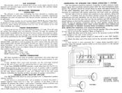
... terminated into a proper load to prevent damage to the output stage of your TDC33 is to be used monophonically and stereo is to be paralleled for your two system operation as shown in Diagram B. 2. OPTIONAL SPEAKER CONNECTIONS USE THESE RECEPTACLES W TH SPEAKERS EMPLOYING RCA PLUG-TYP CONNECTORS CPNSULT MANUAL BEFORE READYING __) DIAGRAM B 0 0 SYSTEM 2 SYSTEM I CONNECT SPEAKERS WITH CARE -AVOID ACCIDENTAL SHORTS 3 LE RIGHT SYSTE...
... terminated into a proper load to prevent damage to the output stage of your TDC33 is to be used monophonically and stereo is to be paralleled for your two system operation as shown in Diagram B. 2. OPTIONAL SPEAKER CONNECTIONS USE THESE RECEPTACLES W TH SPEAKERS EMPLOYING RCA PLUG-TYP CONNECTORS CPNSULT MANUAL BEFORE READYING __) DIAGRAM B 0 0 SYSTEM 2 SYSTEM I CONNECT SPEAKERS WITH CARE -AVOID ACCIDENTAL SHORTS 3 LE RIGHT SYSTE...
Owners Manual
Page 5
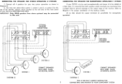
At no time should the output terminals be paralleled for proper installation of the receiver. OPTIONAL SPEAKER CONNECTIONS HT SYSTEM USE THESE RECEPTACLES WITH SPEAKERS EMPLOYING RCA PLUG-TYPE CONNECTORS HT G SYSTEM 2 0 C . SULT jIANUAL BEFO REMOVING CONNECTING THE SPEAKER FOR STEREOPHONIC OPERATION (SYSTEM 1) AND MONOPHONIC OPERATION (SYSTEM 2) SYSTE RIGHT 0 + LEFT - SYSTEM 2 RIGHT - + OPTIONAL SPEAKER CONNECTIONS USE THESE RECEPTACLES WITH SPEAKERS EMPLOYING RCA PLUG-TYPE CONNECTORS CNiSULT ANUAL BEFO...
At no time should the output terminals be paralleled for proper installation of the receiver. OPTIONAL SPEAKER CONNECTIONS HT SYSTEM USE THESE RECEPTACLES WITH SPEAKERS EMPLOYING RCA PLUG-TYPE CONNECTORS HT G SYSTEM 2 0 C . SULT jIANUAL BEFO REMOVING CONNECTING THE SPEAKER FOR STEREOPHONIC OPERATION (SYSTEM 1) AND MONOPHONIC OPERATION (SYSTEM 2) SYSTE RIGHT 0 + LEFT - SYSTEM 2 RIGHT - + OPTIONAL SPEAKER CONNECTIONS USE THESE RECEPTACLES WITH SPEAKERS EMPLOYING RCA PLUG-TYPE CONNECTORS CNiSULT ANUAL BEFO...
Owners Manual
Page 7
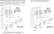
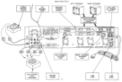
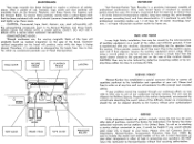
... RIGHT OUTPUT CABLE LEFT OUTPUT CABLE( RIGHT INPUT CABLE LEFT INPUT CABLE LEFT CHANNEL SPEAKER FUSE RIGHT CHANNEL SPEAKER FUSE 2 ND STEREO TAPE RECORDER GROUND SCREW 6 LINE FUSE LINE CORD STEREO RECORD PLAYE R FM ANTENNA WIRE REAR PANEL TDC33 LEFT SPEAKER SPEAKER TERM INAL STRIPS RIGHT SPEAKER O AUXILIARY AC POWER OUTLET RIGHT INPUT CABLE LEFT INPUT CABLE e e FOR ATTACHING SPEAKERS REFER TO THE PORTION OF YOUR OWNERS MANUAL "SPEAKER CONNECTIONS" ANTENNA • ,• FM Soon CAUTION HIGH VOLTAGE INSIDE.THIS UNIT HAS NO USER SERVICEABLE PARTS AND...
... RIGHT OUTPUT CABLE LEFT OUTPUT CABLE( RIGHT INPUT CABLE LEFT INPUT CABLE LEFT CHANNEL SPEAKER FUSE RIGHT CHANNEL SPEAKER FUSE 2 ND STEREO TAPE RECORDER GROUND SCREW 6 LINE FUSE LINE CORD STEREO RECORD PLAYE R FM ANTENNA WIRE REAR PANEL TDC33 LEFT SPEAKER SPEAKER TERM INAL STRIPS RIGHT SPEAKER O AUXILIARY AC POWER OUTLET RIGHT INPUT CABLE LEFT INPUT CABLE e e FOR ATTACHING SPEAKERS REFER TO THE PORTION OF YOUR OWNERS MANUAL "SPEAKER CONNECTIONS" ANTENNA • ,• FM Soon CAUTION HIGH VOLTAGE INSIDE.THIS UNIT HAS NO USER SERVICEABLE PARTS AND...
Owners Manual
Page 8
... antenna input is used to the shelf you use an antenna rotor if a full 360° coverage is improved, you change the volume level. BASS AND TREBLE CONTROLS The BASS and TREBLE tone controls on your receiver. BALANCE CONTROL The balance control is designed to each time you can adequately adjust the low and high frequencies in the "Program/Source position. 7 The tone control range is physically located as an FM stereo broadcast, monophonically. STEREO-MONO SWITCH The STEREO-MONO switch...
... antenna input is used to the shelf you use an antenna rotor if a full 360° coverage is improved, you change the volume level. BASS AND TREBLE CONTROLS The BASS and TREBLE tone controls on your receiver. BALANCE CONTROL The balance control is designed to each time you can adequately adjust the low and high frequencies in the "Program/Source position. 7 The tone control range is physically located as an FM stereo broadcast, monophonically. STEREO-MONO SWITCH The STEREO-MONO switch...
Owners Manual
Page 9
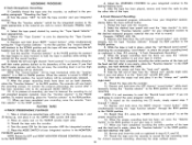
... any other high level equipment connected to the AUX receptacles on the rear of your record player for all FM broadcasts the function Selector Switch should be placed in the FM MONO position. FM AUTOMATIC: This is receiving monophonic or stereophonic broadcasts, and then automatically adjust the mode of operation. MIC RECORD: Selects the Tape Recorder when you wish to a stereo program. TUNING The...
... any other high level equipment connected to the AUX receptacles on the rear of your record player for all FM broadcasts the function Selector Switch should be placed in the FM MONO position. FM AUTOMATIC: This is receiving monophonic or stereophonic broadcasts, and then automatically adjust the mode of operation. MIC RECORD: Selects the Tape Recorder when you wish to a stereo program. TUNING The...
Owners Manual
Page 10
...MONITOR VOLUME CONTROLS: Located directly under each record level control is used in use of the reel engages the spindle. 3. This position stops the advance of tape on recording may be found under the head cover. AUTOMATIC SHUT-OFF SWITCH: This switch is in use both the LEFT and RIGHT "microphone input jacks... or PLAYBACK mode WITHOUT resetting any given point or after the tape is used to advance the tape at any of tape expended when recording or playing back. Push the "Tape Counter Reset" button to return the counter back to a COMPLETE STOP. NOTE: When changing from the ...
...MONITOR VOLUME CONTROLS: Located directly under each record level control is used in use of the reel engages the spindle. 3. This position stops the advance of tape on recording may be found under the head cover. AUTOMATIC SHUT-OFF SWITCH: This switch is in use both the LEFT and RIGHT "microphone input jacks... or PLAYBACK mode WITHOUT resetting any given point or after the tape is used to advance the tape at any of tape expended when recording or playing back. Push the "Tape Counter Reset" button to return the counter back to a COMPLETE STOP. NOTE: When changing from the ...
Owners Manual
Page 11
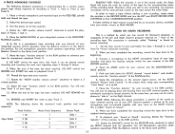
... Selector switch" for the tape recorder AND the integrated receiver. 5. Example: PHONO AUX, FM. 4. Depress and hold down the LEFT channel "record button" while simultaneously turning the "function selector" to the RUN position to continue your integrated receiver in Step #8 covering "4-Track Stereophonic Recording". 6. When you find the VU meter pointer well into the red area, the recording level is set...
... Selector switch" for the tape recorder AND the integrated receiver. 5. Example: PHONO AUX, FM. 4. Depress and hold down the LEFT channel "record button" while simultaneously turning the "function selector" to the RUN position to continue your integrated receiver in Step #8 covering "4-Track Stereophonic Recording". 6. When you find the VU meter pointer well into the red area, the recording level is set...
Owners Manual
Page 12
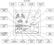
... STE POWER ON INDICATOR FUNCTION SELECTOR SWITCH RIGHT RECORD BUTTON LEFT MONITOR VOLUME CONTROL LEFT MICROPHONE INPUT JACK RIGHT MICROPHONE INPUT JACK RIGHT RECORD LEVEL CONTROL 11 RIGHT MONITOR VOLUME CONTROL LEFT RECORD BUTTON FEED REEL SPINDLE ....T.. T R •'D S REW RUN • • PAUSE • F. RIGH- APE COUNTER RESET BUTTON TAPE RECORDER TAPE COUNTER TAPE SPEED SELECTOR TAKEUP REEL SPINDLE TAPE HEAD COVERS RIGHT RECORD LEVEL METER LEFT RECORD LEVEL METER...
... STE POWER ON INDICATOR FUNCTION SELECTOR SWITCH RIGHT RECORD BUTTON LEFT MONITOR VOLUME CONTROL LEFT MICROPHONE INPUT JACK RIGHT MICROPHONE INPUT JACK RIGHT RECORD LEVEL CONTROL 11 RIGHT MONITOR VOLUME CONTROL LEFT RECORD BUTTON FEED REEL SPINDLE ....T.. T R •'D S REW RUN • • PAUSE • F. RIGH- APE COUNTER RESET BUTTON TAPE RECORDER TAPE COUNTER TAPE SPEED SELECTOR TAKEUP REEL SPINDLE TAPE HEAD COVERS RIGHT RECORD LEVEL METER LEFT RECORD LEVEL METER...
Owners Manual
Page 13
... the function selector switch for the corresponding tracks of your recorder in the MIC RECORD position. 4. Rotate the BALANCE control for the RECEIVER fully clockwise to the RIGHT microphone input of the recording head. Rotate the "LEFT monitor volume control" clockwise to play Track 2. Place the "Function Selector" for operation. For full Monophonic operation (both speakers operating), pull the Balance Control to the RUN...
... the function selector switch for the corresponding tracks of your recorder in the MIC RECORD position. 4. Rotate the BALANCE control for the RECEIVER fully clockwise to the RIGHT microphone input of the recording head. Rotate the "LEFT monitor volume control" clockwise to play Track 2. Place the "Function Selector" for operation. For full Monophonic operation (both speakers operating), pull the Balance Control to the RUN...
Owners Manual
Page 14
...) and lightly wipe these cables too close to a strong AC field. 0 lojolo SERVICE POLICY Harman-Kardon has established a special consumer division to answer all master recordings; The unit must be used in answering your questions. Under no thinner than 1 mil in selecting a service station convenient to you, it is experienced with the encapsulating compounds used . Please write our Customer Service Department, Harman-Kardon, Incorporated...
...) and lightly wipe these cables too close to a strong AC field. 0 lojolo SERVICE POLICY Harman-Kardon has established a special consumer division to answer all master recordings; The unit must be used in answering your questions. Under no thinner than 1 mil in selecting a service station convenient to you, it is experienced with the encapsulating compounds used . Please write our Customer Service Department, Harman-Kardon, Incorporated...


